Before large flat panel displays became available, shadow-mask color CRTs were the only display technology widely available for use in large color graphics terminals. It was the same basic CRT technology used exclusively in color television. Three separate electron guns scanned an array of red, green and blue phosphor dots that were precisely aligned on the inside of the faceplate with respect to a perforated piece of sheet metal. This metal foil, the so-called shadow mask, was positioned a few millimeters from the screen inside the CRT. One electron gun was directed at each color dot array and the three electron beams were intended to be scanned superimposed across the inside of the CRT screen. There were two geometries for the positioning of the three electron guns with respect to one another: a straight line or at the corners of an equilateral triangle. The latter, the so-called “delta gun” arrangement, was usually preferred for higher resolution graphics CRTs because it permitted a larger electron-optical lens to be employed in the gun and thus a smaller electron spot was created. This was desirable for high resolution imaging.
Making certain the three beams scanned one on top of the other, or “converged”, over the entire screen was a much more important requirement in high-resolution graphics CRTs than in consumer television. In graphics CRTs, the user was positioned much closer to the screen and thus was more likely to see a misconverged set of beams. In addition, the negative consequence of this error was much greater since, for example, single-pixel vertical or diagonal lines on a black background were common in text and graphics, making misconvergence all the more visible. For example, if a white capital “R” was intended to be displayed with the blue beam misconverged with respect to the red and green electron spots, a blue R and a yellow (red and green combined) R would be seen, unintentionally simulating a Rolls Royce logo, in peculiar colors.
Converging a color CRT requires significant calibration and time. Calibration also has to be performed in the end-user's geographic magnetic field. Often this was done at the factory in a Hemholtz coil setup for the appropriate geographic region. This ad for a Tektronix 690 color monitor shows the complexity of convergence controls (along with other adjustment controls) in a pull-out drawer. This is the typical labor-intensive method of numerous adjustments for convergence. Click on the image to view the full page ad PDF.

Tektronix engineers, Ron Robinder, Dan Denham and David Bates came up with an ingenious solution. They proposed placing an array of special phosphor features on the backside of the shadow mask, unseen to the user. These features, called “chevrons” would be excited by the scanning electron beams and emit pulses of light when scanned that would be sensed by a photo detector mounted behind a window in the CRT funnel.

As a beam scanned across the chevrons, two pulses were emitted. When the three beams were scanning precisely converged, only two pulses of light were observed by the detector, but when the beams were not converged more than one pulse was detected. The control electronics could then adjust the convergence circuitry to re-establish perfect convergence. This feedback convergence innovation, the subject of a US Patent, was unique to the Tektronix 4115B and was a compelling selling point which contributed to Tektronix domination of high resolution, color computer graphics in the 1980s.
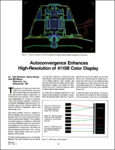
This Volume 7 Number 3 issue of Tekniques describes the auto-convergence technology. Click on the image to view the PDF.