The first PCBs designed at Tektronix were used in the 310 oscilloscope introduced in 1955. There were two double sided paper phenolic PCBs - one for the Y amplifier and one for the high voltage. There were some issues so the 310A, introduced in 1959, reverted back to ceramic strips.
Components were mounted on both the top and bottom of the PCB. The museum is fortunate to have a bare 310 PCB and design files. The PCBs were fabricated 4 up.
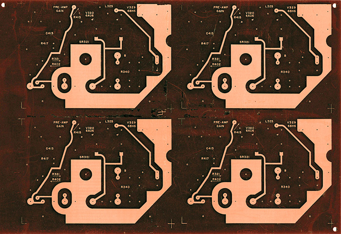
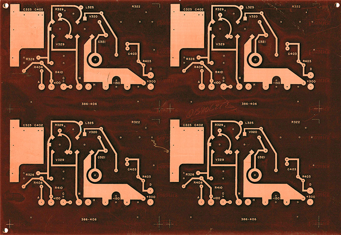
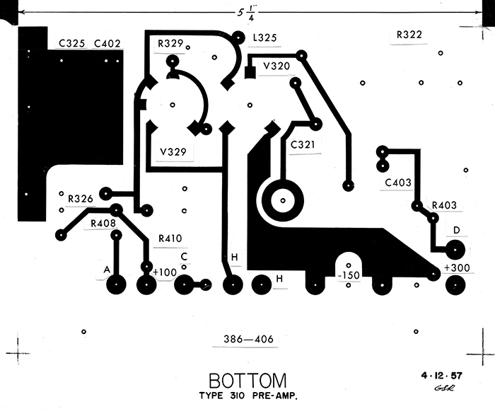
The 4X artwork is not tape but rather filled ink. Note the top (tube side) artwork is labeled bottom and are both dated after the introduction of the 310. GSR on the artwork likely refers to George S. Roussos.
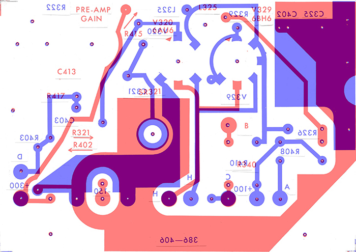
This composite image shows the two layers superimposed.
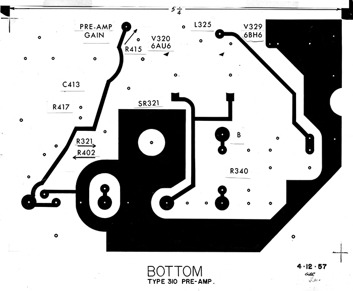
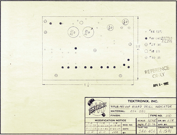
The drill chart is dated August 21, 1956 and shows the bottom view.
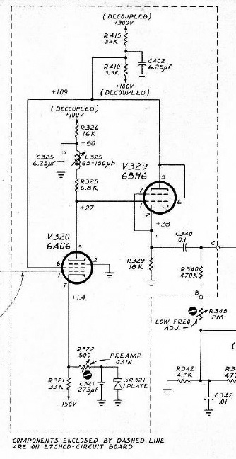
This schematic shows the PCB schematic.
This image from the service manual shows the components mounted on both sides.
This photo shows the preamp PCB.
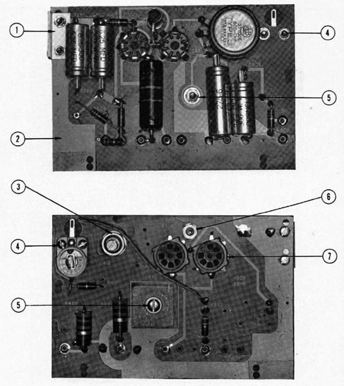
These two photos show the high voltage PCB.
We have a Tektronix Printed Circuit Boards 1969 video on our Video Gallery.
The 360 Indicator Unit was designed around the same timeframe with a PCB. More information can be found on the 160 Series Instruments page.
This article on early PCB fabrication appeared in the November 10, 1955 TekTalk. The Printed Circuit Department consisted of a single employee, Don Olson. It mentions the PCB experiments with the 310, 360, and 123 instruments.