
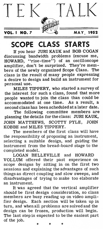
Tektronix organized a scope class based on a survey of employees who wanted to design and build an oscilloscope for their personal use. This May 1952 TekTalk describes the class. We believe additional motivations for the class were to help enable new ideas, concepts, and circuits for scope designs to be tried out and evaluated and it also to indicate resources in the company that could be better utilized in design engineering.
John Kobbe describes the Scope Class in his story "My Early Tektronix Days" on the Employee Stories page.
With Tek’s blessings, a group of five or six of us formed a scope class to design and build an oscilloscope. We would not copy anything and keep it as simple as we could. A month or so on, we had the vertical system, horizontal amplifier, and CRT circuits (except the unblanking). The vertical was to have a 10-1 variable gain, 10 times and 100 times attenuator, no signal delay line with about 3 or 4 MHz band width.
We were having problems figuring out a simple time base (sweep) circuit. On a coffee break I cornered Dick Ropiequet, who had just finished a wide range sweep for the 315 scope, he described all the functions of an idealized sweep circuit. The 315 sweep was more complicated than what we wanted to use, so I set out to find a simple way to keep all the needed requirements but kept coming to dead ends. Finally a circuit made all the way around the loop and was simple enough for our scope.
The scope class was fairly well known within the company. Sandy Sanford and his secretary had their desk just through a door on the other side of the wall from my bench. One of Sandy’s job was to take care of field technical problems. When he didn't have an answer, it was easy for him to step through the door and discuss the problems with us. One of the common problems was the intensity (brightness) needed adjusting after a duty cycle change. Not too bad if it got brighter but when it disappeared the customer would sometimes get totally lost. The unblanking not only needed to be solved for our scope class but for Tek’s new designs. I decided to start a list of all different ways I could think of and adding to the list for the next week or so, then picked the one that looked most promising which was the floating power supply. The first thought was that it was too complicated, but when you look at how it is done, it isn't really that bad.
I came in early one morning and put together needed circuitry, hanging it out the side (so it would be easy to put back to normal) of an upside down scope which I was supposed to be calibrating. Went into engineering, explained the idea and like my first thoughts, they were doubtful. When they found out that there was one hay-wired together on my bench, Frank Hood said he would come look at it, as he needed a better unblanking system for a new portable scope ( would be called the 310). He liked what he saw and thought that some more engineers should come look at it. Frank also wanted our sweep for his new scope.
I soon found myself in engineering and the scope class came to an end, but I guess you could say it sort of lives on as a 310.
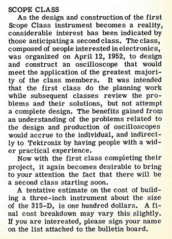
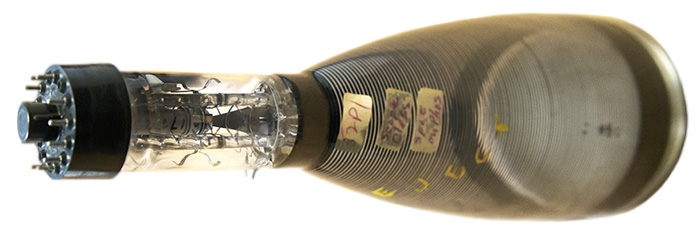
This June 1953 TekTalk features an article on a second upcoming scope class.
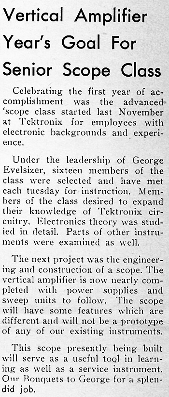
This December 5,1954 TekTalk features progress with the scope class. Since it mentions first year of accomplishment for a class started in November of 1953, it must be a follow-on scope class.
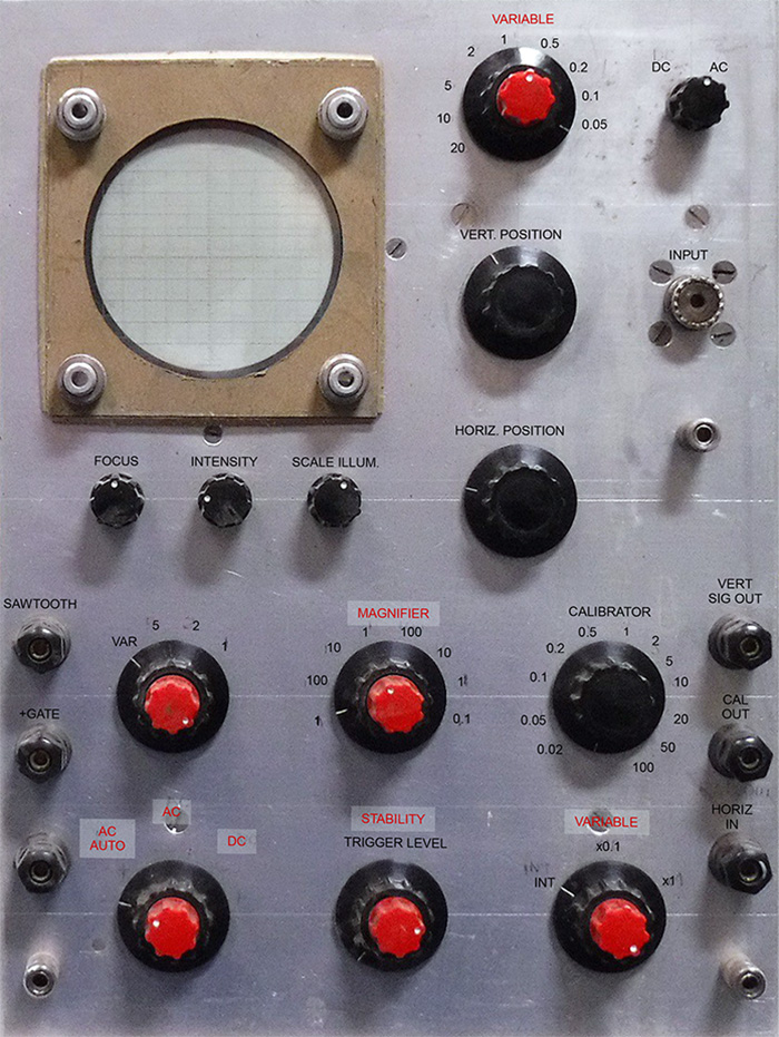
The museum has an oscilloscope from the scope class. We have no information as to who the designers were nor any documentation. It is built on two chassis, one for the power supply and one for the oscilloscope.
Our restoration engineer Phil Crosby brought this oscilloscope back to life. This photo shows the first waveform on this oscilloscope in 65 years! Nice work, Phil.
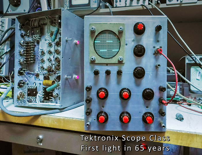
The front legends are hand-drawn and faint. This photo shows what the various controls and settings are.
This February 1958 TekTalk describes the start of another scope class.
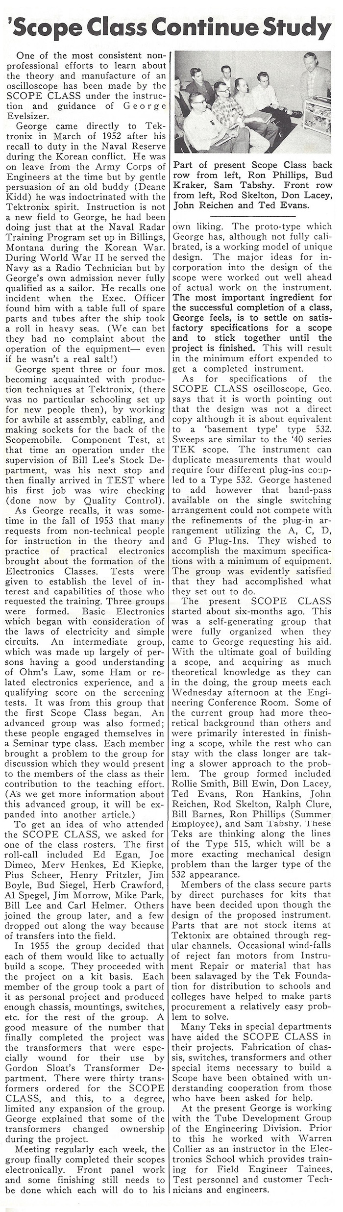
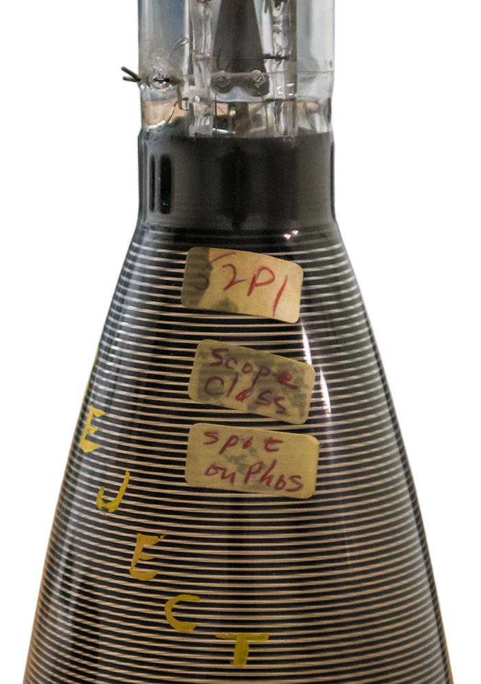
Here is an interesting find. We were working on a non-production 575 Curve Tracer and when we pulled the CRT we found a reject with a Scope Class sticker on it!
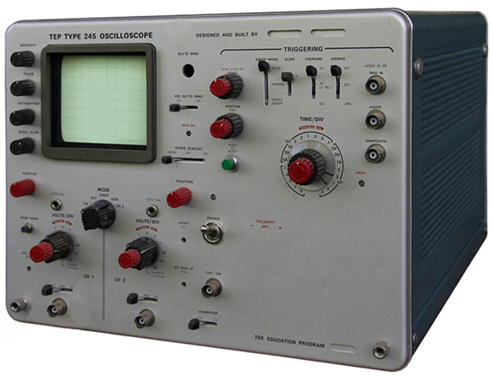
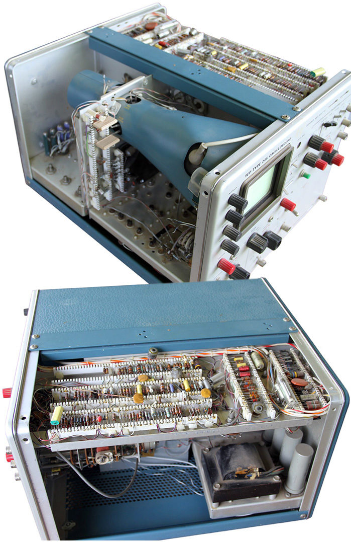
In the late 1960s there was yet another scope class run by the Tektronix Education Program (TEP). This class appears to be for individuals to build their own scope from a standard design. It was nomenclated the TEP 245 and parts could be purchased for $160.00. It was hand wired with ceramic strips and used circuits from the 422 and 453. Daniel Fortune sent us these photos of his TEP 245.
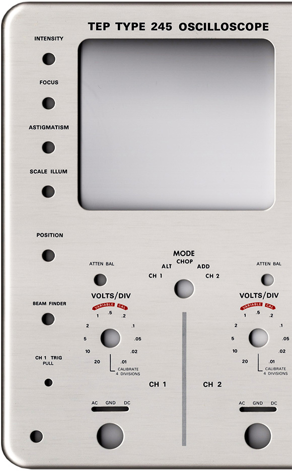
The museum has the panel for the TEP 245 oscilloscope. This panel has additional legends in the lower right corner for a voltage bridge that Daniel's doesn't have although his has the red Polarity Off legend. Note that none of the bridge holes have been punched. The photo is split to show it higher resolution for readability.
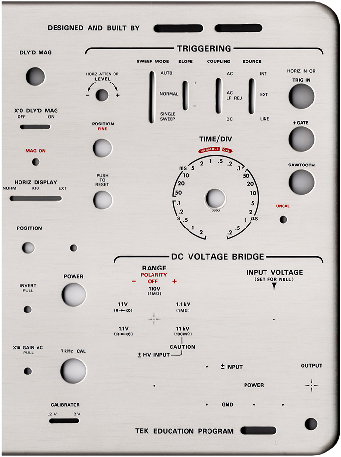
The DC Voltage Bridge was an option that could be added to the kit to measure voltages. It used a very accurate 11 Volt supply with a .1% step divider and a 10 turn pot. This voltage was sent to a chopper and would display a 60 Hz. square wave on the oscilloscope. When the signal was nulled out you could read the DC voltage on the divider.
We do not know when scope classes ended. This information on the class is from Forrest Burton on his scope class build.
In 1969-1970, during the Fall, Winter, and Spring term the Tektronix Education Program offered a class on “Oscilloscope Design”. The course number was “TEP 2.021”, and it ran for 60 hours of class time plus a lot of working at home time.
The course instructor, Don Schwab, led us through understanding the basic circuits found in the Tektronix scopes. He then got to the “design” part of the class which was to cover all of the things that went into actually building an Oscilloscope. We were to learn first hand things like circuit board layout, circuit board fabricating, and component selection as well as mechanical design and layout.
At that time, the Tek 422 portable scope was very popular, so we used the 422 CRT and power supplies (high voltage and low voltage) as the basis of our project. The Vertical Amplifier board was from a Tek 453 scope. Using the 422 horizontal sweep circuit schematic, we laid out our own circuit board version of that circuit. The printed circuit board facility was kind enough to manufacture the number of boards we needed (one for each scope), and when we assembled the board, we were astounded when it actually worked!
A cabinet from a Type 561 scope power supply was used to house the project as it gave a lot of room to work in, and it would not look like any scope that Tektronix was selling.
Due to the amount of work required to design and build this unit, many of the class members gave up before the end of the 60 hours + many home hours, and to my knowledge, my scope was the only one to actually be completed. Some of the students did not appear to have the electro-mechanical skills needed – nor the time needed to finish this project.
For reasons I do not remember, the front panel lettering was never done in the class, so I used “rub-on numbers” to provide the markings around the controls. I suspect that the class was over before the panel layout could be done.
My finished scope has about a 30 MHz band width, the 422 was a 15 MHz scope, but because we used a 50 MHz 453 vertical board, the resulting band width was better than a stock 422. The only major circuit that is missing is a delayed sweep which was not included on our version of the horizontal board.
I used my scope in my home lab for over 20 years, and never had to repair any part of it. Despite the fact that it has been on a shelf in my garage for another 20+ years, it still functions just as it did when it was made.