A delay line is used in an oscilloscope to view the leading edge of the trigger event. The trigger signal is usually derived from the vertical signal path. The trigger and sweep circuitry need about 60 ns to start so there is no signal display during this time. A delay line placed in the vertical signal path after the trigger signal will result in the ability to display the trigger portion of the signal.
The Type 113 was a large stand-alone suitcase style 50 ohm delay line introduced in 1960 to augment sampling applications such as a Type 110 pulse generator and trigger, and a Type N sampling plug-in which does not have a built-in delay line. The Type 113 continued in production until 1973.
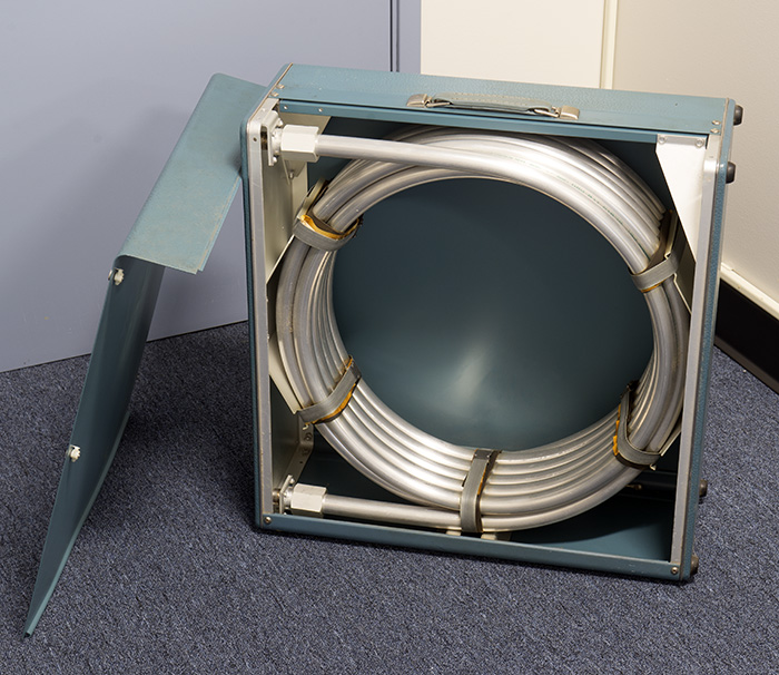
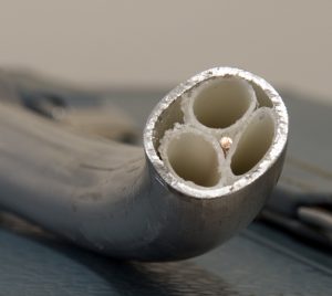
The actual delay line, called “Spir-o-line”, was not manufactured by Tektronix. It was called Spir-o-line because the large center conductor (about the size of a pencil) was held inside the line with a spiral of polyethylene tubes (largely air). This image is of the 519 delay line which has a much smaller center conductor.
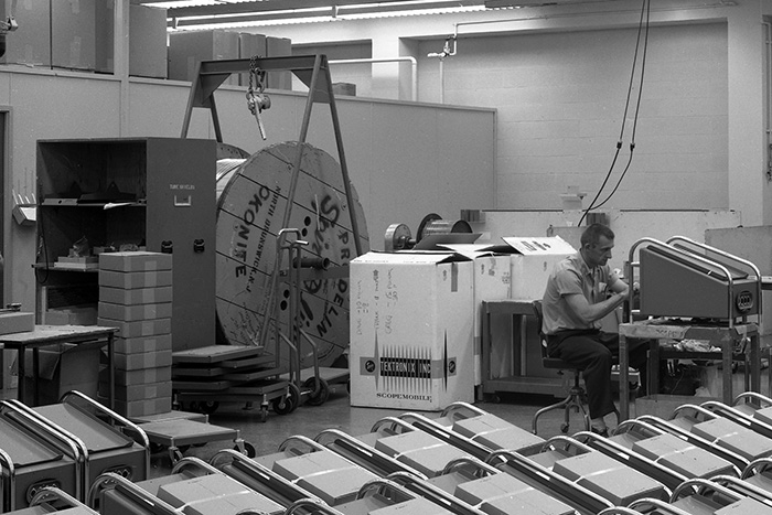
Spir-o-line came on very large spools as can be seen in this image.
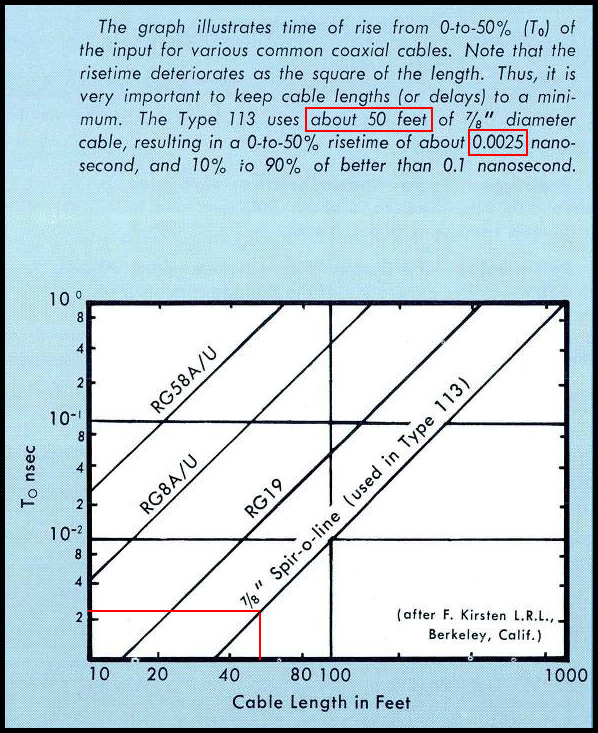
Kerns, Kirsten, and Winningstad at Berkeley came up with the equation for transient response for a skin effect limited delay line (Norm Winningstad later came to Tektronix). An updated version of their original work is at lss.fnal.gov and the resulting rise time calculation of 2.5 pS is specified for the 113 delay line.
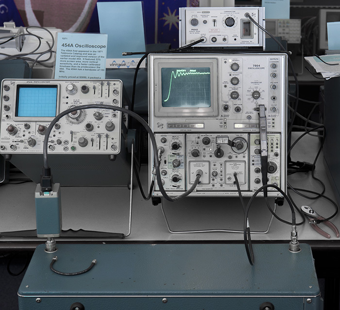
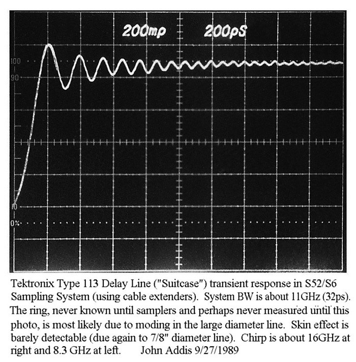
No one could measure the actual rise time so no one challenged these calculations. In 1989 John Addis of Tektronix measured the transient response of the 113. As can be seen in the following oscilloscope image, the original calculations were way wrong, since at best, the rise time is about 180ps.
The museum configured a 7904 mainframe with a 7S12 TDR/Sampler plug-in to reconfirm the Type 113 delay line rise time.