Effective measurement of television signals requires features not found in general purpose oscilloscopes. Television signals spend about 80% of the time conveying variable content, leaving only the remainder of the time to convey information about reference levels and the times at which they can be sampled. Since the video content must be presented on a 2D display, a means of mapping the signal into the display space is needed.
In the days of vacuum tubes, memory was expensive. Volatile storage of just one bit cost at least a few dollars. Video is displayed in a raster form - left to right, top to bottom, so the display raster had to closely correspond to the scanning raster. Accordingly, the video signal featured negative-going pulses providing an X reference and a wider group of pulses providing the Y reference. A pulse had to occur for each horizontal line and two consecutive fields of information had to be precisely interlaced to produce a video frame.
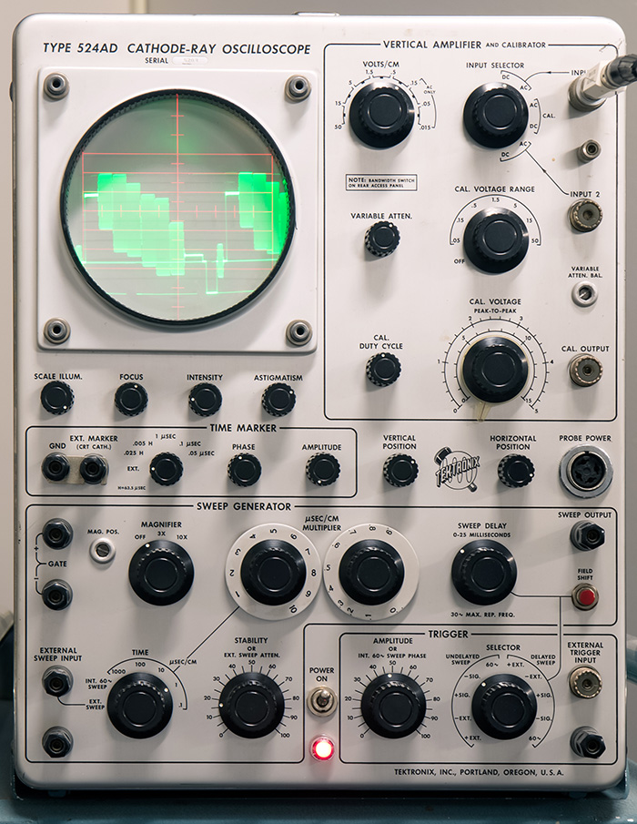
The 524 was designed by Cliff Moulton, who had designed the features that, when added to the 514, turned it into the 524. The 524 contains circuitry needed to identify the timing information irrespective of the video content. Other features of the video signal were blanking pulses that delineated the time of video versus no video. In the 1950s, this was all done using analog circuitry dependent on resistors, capacitors and vacuum tubes, not a very stable setup. Accordingly, the 524 also featured time markers generated by relatively stable L-C ringing circuits to ease the measurement of sync and blanking pulse widths.
One notable feature is that there are no negative power supplies. The vertical amplifier was AC coupled only, and it employed an optional "sync tip clamp" which actively sets the bottoms of the synchronizing pulses to a position determined by the vertical position control, making level measurements easier, particularly when a test signal is shared with active video.
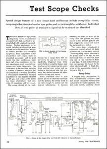
Finally, the 524 had a line selector whereby individual lines in a field or frame could be examined (albeit dimly). The 524 appeared as a 524D in short-form catalog 5207, presumably July 1952. A TV adapter, the 124 appeared later, having sync separation, vertical sync detection and line selector features of the 524, allowing other triggered oscilloscopes to do many of the things that the 524D, (later AD) could do. This January 1953 Electronics article, authored by Cliff, features the 524. Click on the image to view the PDF.
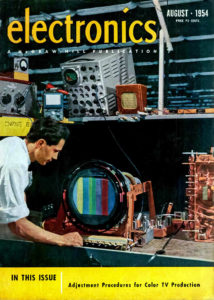
This cover of the August 1954 issue of Electronics shows the 524D used in the emerging color television industry.
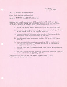
This January 21, 1955 memo describes the differences between the 524D and 524AD. Click on the image to view the PDF.
The museum has a 524AD on display.
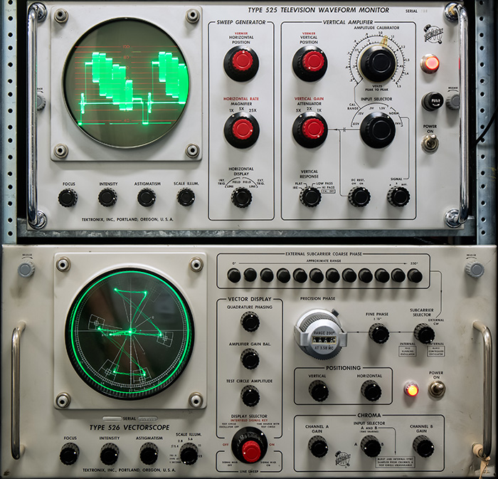
TV waveform monitors are specialized oscilloscopes used for monitoring TV signals in studios and transmitters. The 525 was the first waveform monitor that Tek produced, first appearing in the spring 1955 short-form catalog. It was probably not a coincidence that the 525 was named thusly, since the number of horizontal lines per field in the U.S. TV standard was 525.
It also employed a phantastron sweep generator, a kind of op-amp based ramp generator preceding the later Miller integrator timebase circuits found in most Tek oscilloscopes after the mid-50s. The phantastron sweep circuit was derived from the 524, which appeared in 1952.
In 1955, the National Television Standards Committee (NTSC) issued a standard for a compatible color television system, an enhancement of the earlier 525 line monochrome system.
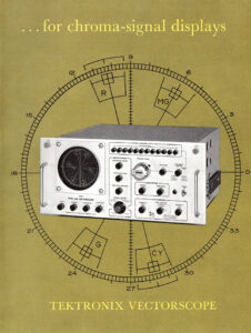
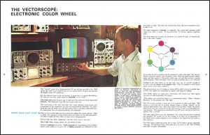
In late 1956, Charles Rhodes who had recently joined Tek, working with Ron Olson, started work on an oscilloscope called the vectorscope. Its primary display mode was an X-Y display of the orthogonal R-Y and B-Y components conveying color information about each point in the raster. So the signal can be represented as containing three components, Y, R-Y, and B-Y. The 526 did not display Y, that was a job for the 525.
Since at a given frequency (in this case 3.579545MHz +/- 11Hz), the phase change of a vector can be represented as a change in delay, the 526 employed a 20 turn precision helical delay line to shift the phase of the demodulating subcarrier, allowing phase measurements to be made from a helidial.
Sales of the 526 began at a brisk pace in 1959, but began to taper off as customers began to witness the poor performance and stability of the first-generation color equipment. This August 1966 brochure details the 526 vectorscope. Click on the image to view the PDF.
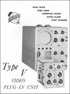
This 1961 brochure describes the proposed Type V Video plug-in, designed by Phil Crosby, Larry Biggs, and Ron Olson. It was intended to replace the Type 524 oscilloscope but never went into production. This brochure has numerous sweep speed mistakes on the scope images on page 3 (click here to view the corrections). Click on the image to view the PDF.
As color equipment manufacturers used the 526 to diagnose their deficiencies,
performance improved, color became more acceptable and sales of receivers, studio equipment and program content rapidly increased. Executives working in the TV industry stated that the vectorscope hastened the introduction of color television by at least three years.
This article on the vectorscope appeared in the Summer-Fall 1968 issue of TekTalk. Click on the image to view the PDF.
The museum has a 525 waveform monitor and a 526 vectorscope on display.
Tek began building glass CRTs with rectangular envelopes in 1959. They were first used in the RM561 oscilloscope and the 527 and rack mount waveform monitors that first appeared in the 1961 catalog. The 527 and RM527 were also the first waveform monitors to be offered in two physical configurations, a 5.25" high rack mount and a 10.5" half-rack wide cabinet model, popular because it enabled two camera control units to be housed in the same rack, useful for operating in cramped spaces.
The 527 used mostly vacuum tubes, its single transistor producing a calibrator waveform (as the sole transistor in the 526 functioned as a test circle oscillator). It employed the then-new muffin fans that moved a decent amount of air, but could fit in the limited rack height. It employed a "back porch clamp" placing the video blanking level on the screen at a location determined by the vertical position control, simplifying level measurements. The first 527s were delivered for the new KNXT-TV CBS Technical Operating center opening in Los Angeles in early 1960.
In the 1960s, as transistors began to equal and exceed vacuum tubes in performance, some projects were canceled because they were judged to poorly fit into the anticipated future. However, those design efforts often later became valuable assets. The 527 appeared at a time when color TV was taking off, but it wasn't until well after the 527 appeared on the market that a mostly solid-state waveform monitor could be built. The need to use test signals buried in the vertical blanking interval necessitated attention to CRT and amplifier design in order to achieve the needed writing speed performance. The 529 replaced the 527 and employed a transistor-vacuum tube hybrid technique to achieve the needed voltage swing performance using a monoaccelerator CRT. The accelerating voltage was 5.5KV, later increased to 6.6KV, in order to achieve the requisite brightness. Many features such as the back porch clamp were both simplified and improved over previous implementations. The 529 and R529 enjoyed a product lifetime of more than 11 years. The museum has a 529 waveform monitor and 520A vectorscope on display.
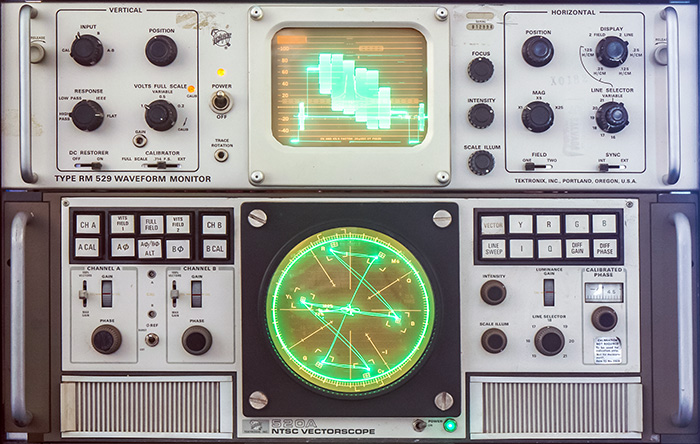
In 1965, after the release of the 529, it was clear that similar upgrades were needed for the 526. It had issues with drift and acoustic noise, mostly due to the large number of vacuum tubes. A demodulation technique using fast transistors and hot-carrier diodes in a Baker clamp configuration greatly reduced carrier feed-through. Delay matched low-pass filters made full decoding to red, green and blue outputs possible. In fact modified 520 decoded outputs were used to produce many of the first chromakey special effects.
Sampling deflection plate voltages during horizontal blanking ensured that the on-screen spot location was precise. Steve Roth conceived of an inductively coupled goniometer to provide continuous phase rotation on each of two time-shared channels (no brushes or slip rings), greatly simplifying color camera setup. A calibrated phase shifter with 0.1 degree resolution over a +/- 15 degree range in conjunction with a trace overlay technique allowed precise measurement of differential phase distortion. Why was that important?
In the days before digital and satellites, TV was conveyed across the nation over microwave links averaging 50 or 60 miles in length. 60 analog hops meant that a relatively small amount of signal degradation could cascade into a serious problem and bad links needed to be identified. Design of hardware that could detect 2% of an analog problem was a big challenge. However, taking on and solving that challenge was the big reason that the market share enjoyed by the TV Division was so large. The 520 also spawned the 521, which was compatible with the emerging European PAL system.
We have a video of the 520 Vectorscope on our Video Gallery.
While the 521 was under development there was one major obstacle - no test signal. Tektronix found that the only commercial source for a PAL color bar signal had a delivery delay of 18 months. Steve Roth, the engineer who designed the goniometer, offered to take on the task of designing a PAL test signal generator. Using the new digital ICs of the era he designed two generators in six months that generated PAL color bars, linearity staircase and convergence signals. Although the 141 started out as a specialized "test fixture", Tektronix knew they could launch a product line of test signal generators.
In order to demonstrate 521s, the "test fixture" was the only source Field Engineers would use. While the 521s were demonstrated to customers they naturally asked about the "test fixture". Soon management understood that Tektronix could enter a new product area. The PAL "test fixture" became the 141 and the 140 NTSC version quickly followed since the signal is similar but simpler. The 141 also provided means of turning off or inverting certain signal components, features that simplified problem identification. Those features turned out to be popular with NTSC customers as well.
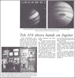
This April 4, 1975 TekWeek features an article on NASA's use of television products to view the planet Jupiter. Click on the image to view the PDF.
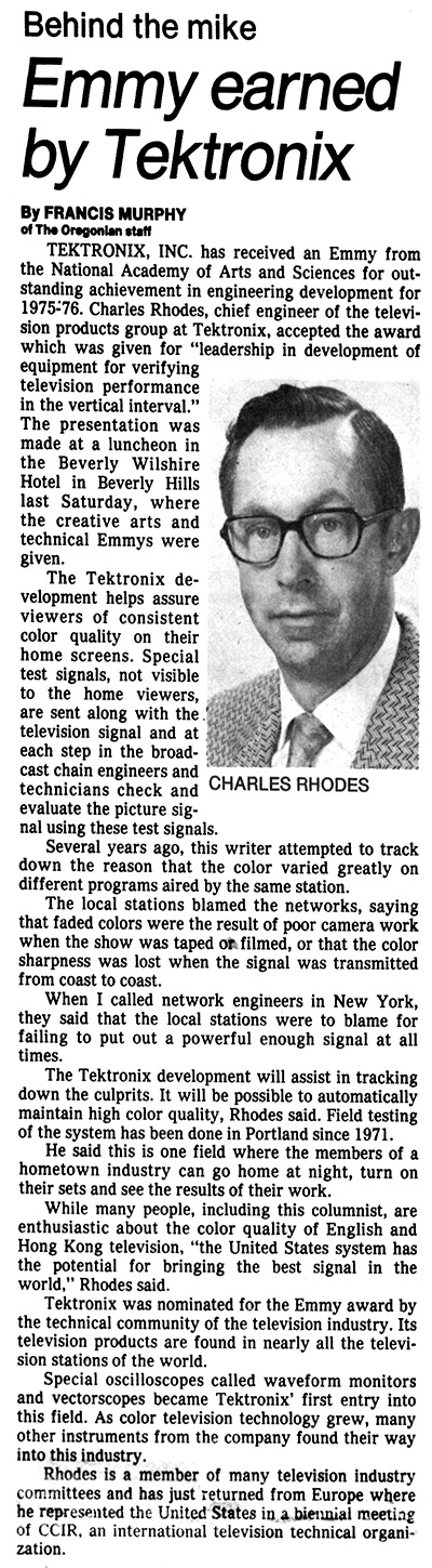
This May 22, 1976 Oregonian article features Tektronix first Emmy and describes some of the television products and their use in delivering quality signals to consumers. Tektronix and Grass Valley Group received a number of Emmy awards for their impact on the television industry. More information on these are on our Emmy Awards page.
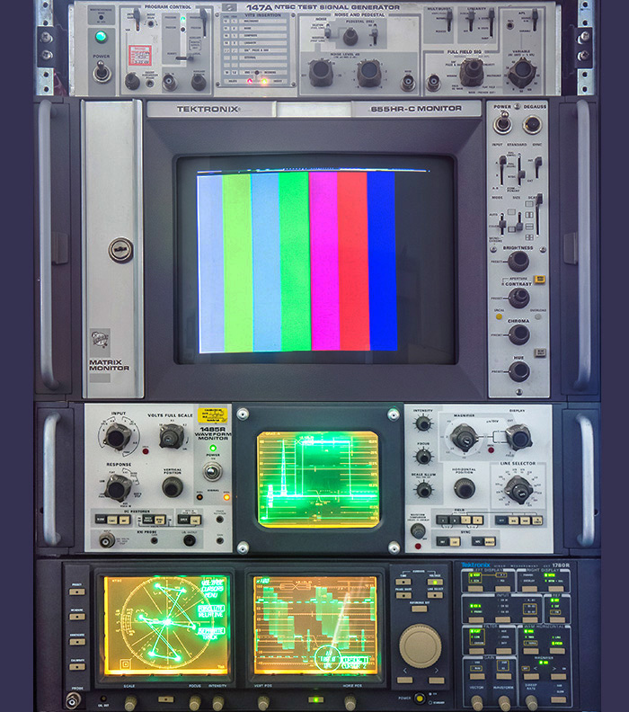
The museum has a number of later products including the 147A NTSC Generator, 655HR-C color monitor, 1485R Waveform Monitor and 1780R Video Measurement Set also on display.
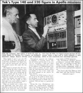
This July 25, 1969 TekWeek features an article on Charlie Rhodes, the Type 140 NTSC Signal Generator, and the Type 520 Vectorscope used for the Apollo moon mission. Click on the image to view the PDF.
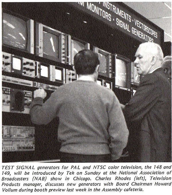
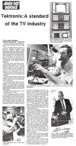
This April 7, 1972 TekWeek features Charlie Rhodes and Howard Vollum at NAB.
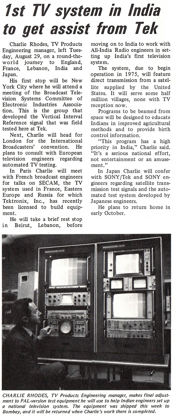
This September 1, 1972 TekWeek features an international trip by Charlie Rhodes.
These two July 27th and August 3rd 1979 TekWeeks feature Area Rep information on the Television Products Business Unit and the industry. Click on the images to view the PDFs.
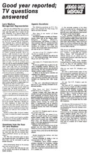
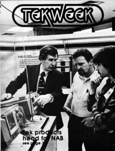
This April 8, 1983 TekWeek features the new products to be shown at NAB. Click on the image to view the PDF.
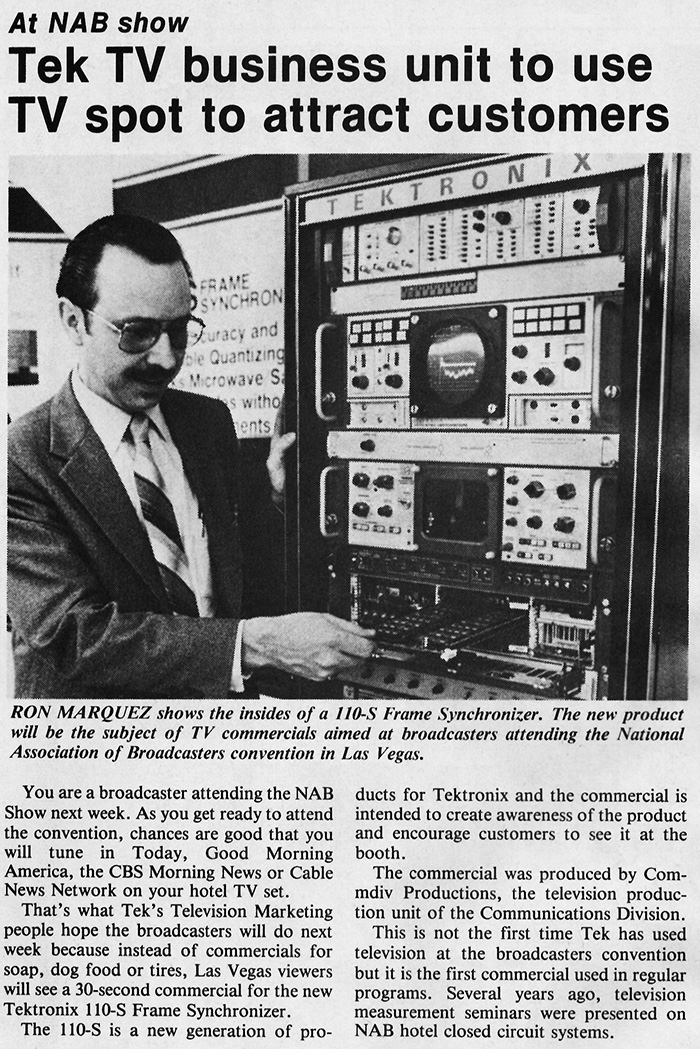
This April 8, 1983 TekWeek also features Tektronix commercials to be shown at NAB.
The Profile Professional Disk Recorder PDR-100 was introduced in 1995. It could handle 4 simultaneous video streams and won Tektronix's 9th Emmy in 1996. Click on the image to view the PDF.
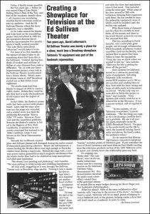
This April 21, 1995 TekWeek article features Tektronix products used in the rejuvenation of the Ed Sullivan Theater. Click on the image to view the PDF.
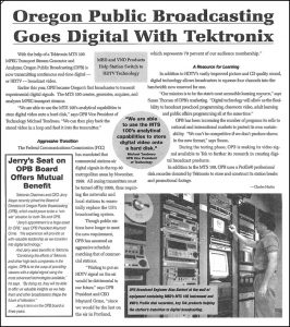
This January 23, 1998 TekWeek features Tektronix products used at OPB for their continuous HDTV transmission. Click on the image to view the PDF.