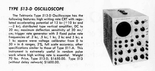
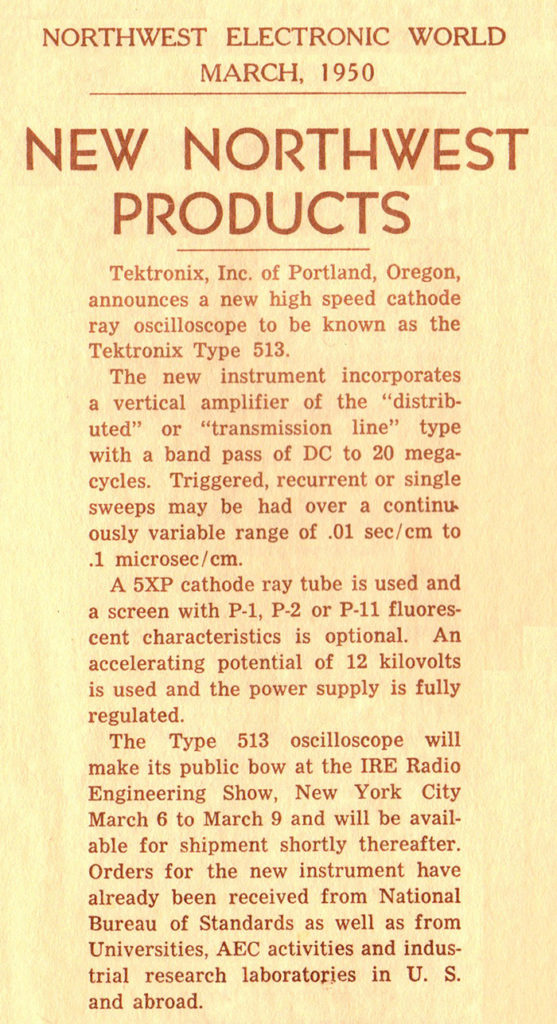
The Type 513 “Wide Band” Oscilloscope was first shown at the 1950 Institute of Radio Engineers meeting in New York City in March. The 513 appeared in the Tektronix June 1950 Short Form Catalog for $1600. The 513D which included the delay line sold for $1650.
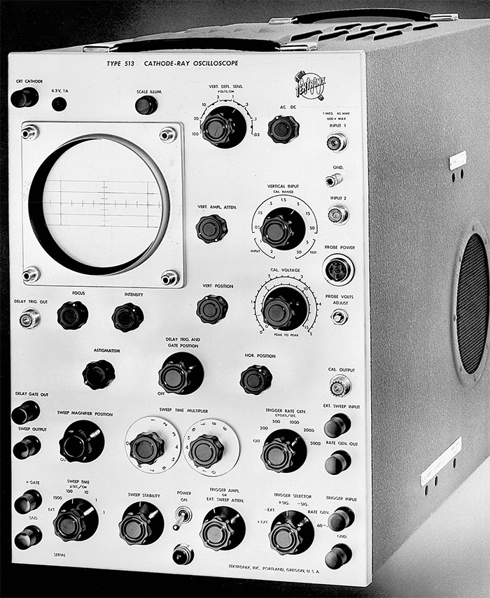
The Type 513 Instruction Manual describes the instrument as:
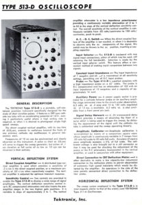
The Tektronix Type 513D is a portable, self-contained, precision instrument specifically designed for displaying a plot of the variations with respect to time of a voltage pulse or wave, with self-contained means of measuring its duration and magnitude. It is primarily intended for study of short duration pulses.
It features a 5XP type cathode-ray tube with an accelerating voltage of 12KV, making it particularly useful where a high writing rate is required, or where it is desired to photograph single, high speed sweeps. This handbook describes its characteristics, basic principles, operations and maintenance.
This advanced information for the 513 appeared in the March 1950 Northwest Electronics World magazine (really a 12 page flyer).
This excerpt from the August 1950 catalog describes the 513. Click on the image to view the PDF.
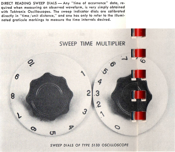
This excerpt from the 1951 Tektronix Catalog highlights "Fingertip Controls" of the 513D Sweep Dials. Click on the image to view the full "Fingertip" Control page.
Howard Vollum, in his interview by Jim Castles on May 8, 1984 in preparation for the 40th anniversary book, states:
The 513 was very similar to the 511 in philosophy, except it had a faster sweep and it had a distributed amplifier which we were also using in the 517 – I mean we were using a similar type of amplifier in the 517. The 513 was an approximately twenty megahertz oscilloscope, eighteen or something like that. It was not fundamentally different from the others except for the distributed vertical amplifier.
Miles Tippery, one of the four founders of Tektronix, made these comments about the 513 in his book My Years At Tektronix 1946-1953:
There appeared to be a considerable demand for an oscilloscope something on the order of the Tektronix Type 511 but with a wider band vertical amplifier which could operate at still higher frequencies than the 511. A brighter cathode-ray tube, higher gain in the vertical amplifier, and some other features which I don’t entirely remember 45 years later.
Design for this instrument, to be called the Type 513, was soon begun, and the assignment fell largely to another recruit for the engineering department—a local man named Frank Hood. Frank had been involved in working with a radio parts supply company before World War II, and through this connection had made contact with Murdock and Vollum. As Frank was a methodical worker, much on the order of Belleville and Rhiger previously described, plus handling our in-plant photography, it obviously was going to take quite a while for this new Type 513 to be ready for manufacture. We decided to simultaneously make an entirely new version of the Type 511 which would incorporate the 511’s good features but would add some features of its own. It was expected to become a replacement for the 511 as soon as it could be brought into production. However, as usual, getting it through engineering and testing and into production took much longer than Howard had expected; but eventually it was produced and it did replace the 511. This new instrument was known as the Type 514.
Frank Hood, in his Tektronix, The Early Days stories writes:
I was privileged to be the project engineer in designing the Type 513, a scope with about twice the bandwidth and brightness of the 511. This instrument also used a distributed amplifier with 14 tubes in the output stage and with a 12 thousand volt power supply.
Atomic and Hydrogen bomb tests were being conducted in the South Pacific in the early 1950's. The main measuring instruments for these tests were Tektronix 517’s and 513’s. Dozens of scopes were used to record an event that only lasted a fraction of a second. Many were destroyed, but they had served the intended purpose. Others were contaminated with radioactive fallout and were sent back to Beaverton for cleaning and recalibration.
The 513 Oscilloscope had a bandwidth of approximately 18 MHz and a sensitivity of 30 mv/div. It used a “distributed” vertical amplifier which makes use of many pairs of tubes in parallel to achieve this performance. It can synchronize on signals as high as 10 MHz.
The 513 was first introduced with the 5XP CRT from DuMont was replaced after SN 1887 with the first Tektronix made CRT, the T51. This is the same CRT used in the Type 531 and 535 oscilloscopes. Unlike the DuMont CRT that used four discrete increasing acceleration voltages (and four separate anode buttons), the T51 employed a pioneering resistive helical anode connection that gradually increased the acceleration potential and avoided the deflection distortion caused by the abrupt high voltage changes found in the DuMont CRT. More information on the T51 can be found on the Tektronix CRT History page in Part 2.
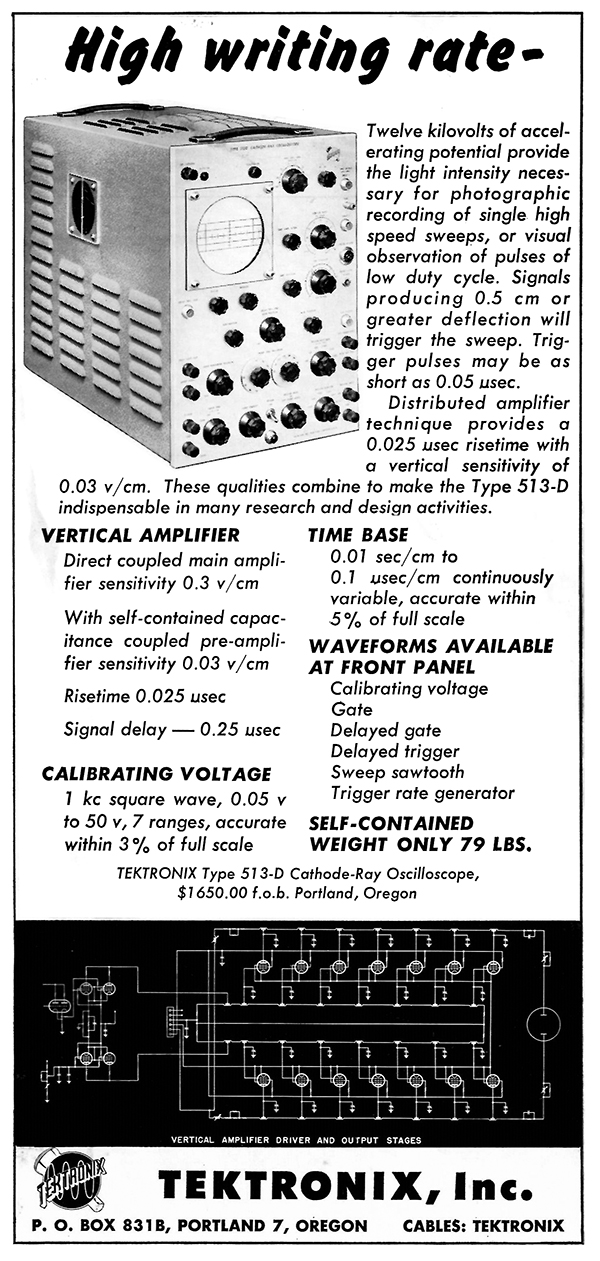
This ad for the 513D appeared in the April 1952 issues of Electronics and Proceedings of the IRE.
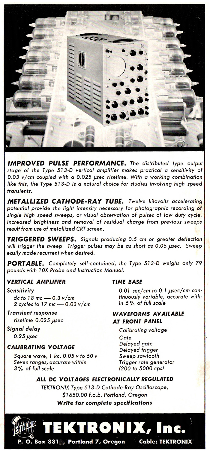
This ad for the 513D appeared in the June 1952 issue of Electronics.
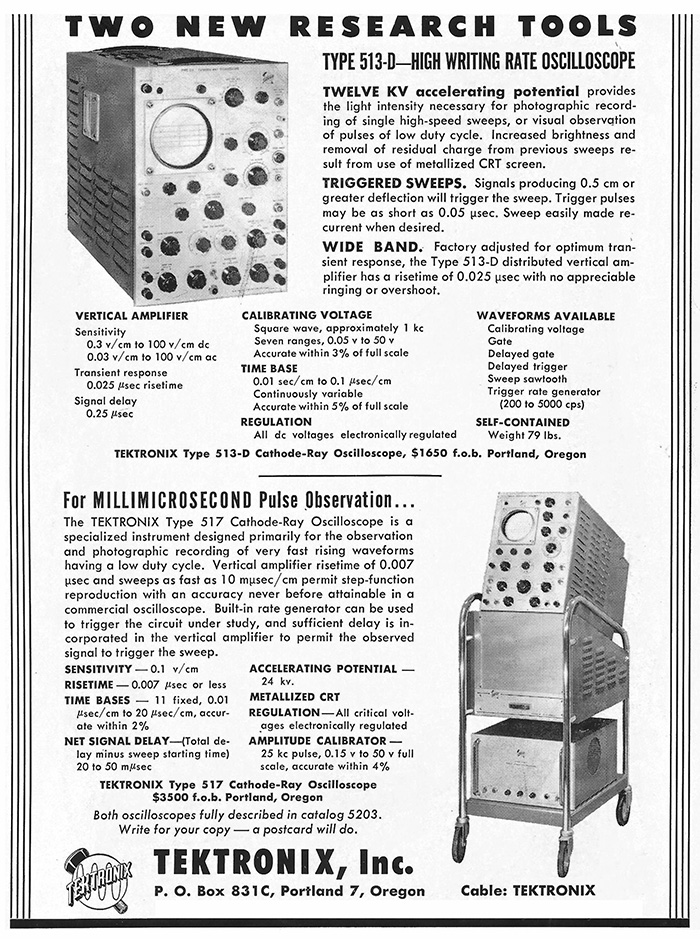
This ad for the 513D appeared in the January and April 1953 issue of The Review Of Scientific Instruments.
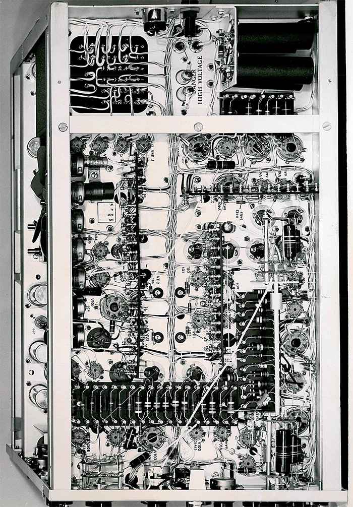
These two photos are from a Tektronix Photo Album, date unknown.
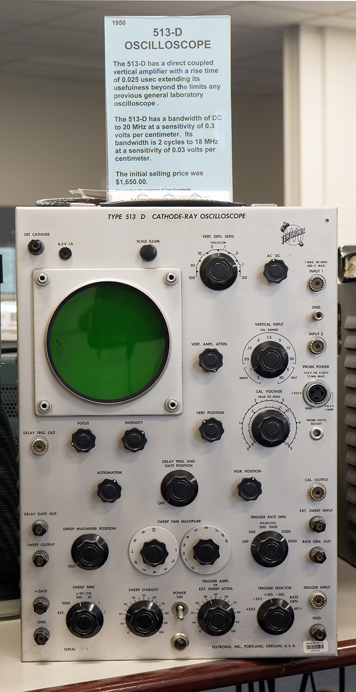
We have a Type 513D oscilloscope on display at the museum.
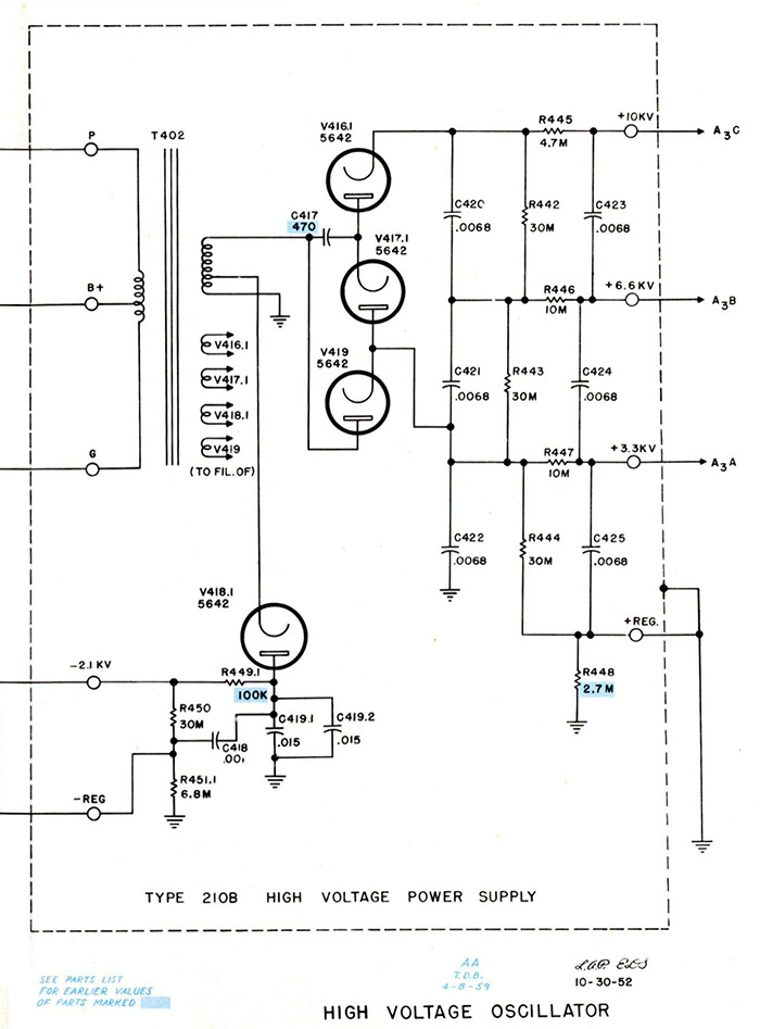
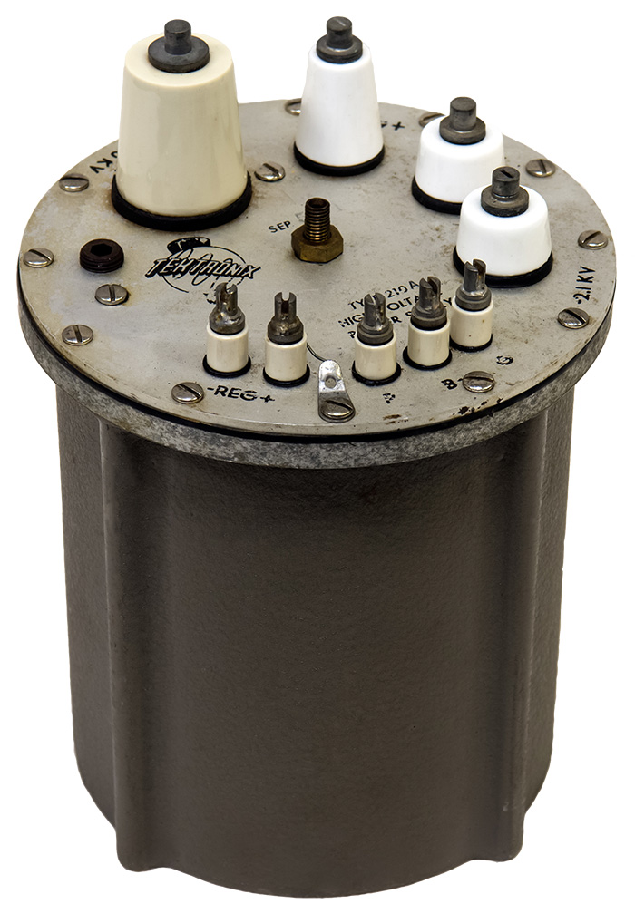
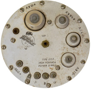
The 513 had a unique approach to the high voltage power supply. The transformer, tubes and associated components are mounted in a large metal can with the high voltage terminals on the top. The circuitry can be seen inside the dotted lines of this 513 high voltage power supply schematic.
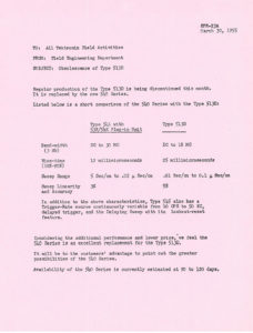
This March 30, 1955 memo discusses the obsolescence of the Type 513 oscilloscope. Click on the image to view the PDF.