
We have some early 1980's oscilloscopes at the museum which used the Mostek MKB36000 ROMs which are known to deteriorate over time (e.g. FROMs - Forgetful Read Only Memories). One is the Tektronix 7854 Oscilloscope with Digital Storage. The ROM board contains four ROM sockets, a FPLA, and two EPROMs for patches (i.e. updates) to the masked ROMs. The FPLA "traps" addresses and the EPROMs supplies the new data.
The vintageTEK museum offers a replacement ROM board. It was designed by one of our volunteers and is available on our eBay store. It replaces the original ROM board and will work with SN below and above B100000.
7854 Rom Card Instructions V1.1 2024
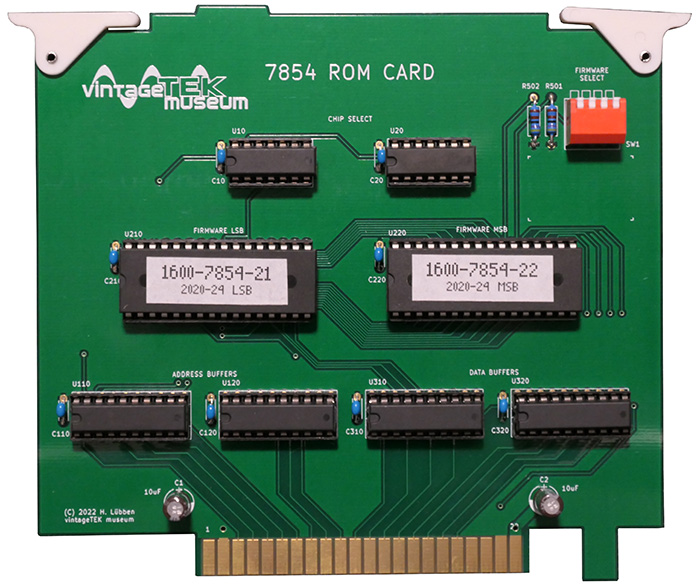
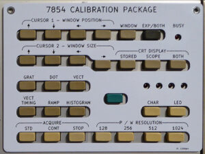
Both the regular and diagnostic firmware are included, chosen by a top-accessible DIP switch. A keypad overlay for diagnostic mode is included.
Our previous solution to the issue was EPROMs on adapters. It is listed here for historical reference.
Someone read the contents of the ROMs together with the patches and EPROMs to make binaries so larger EPROMs could replace the ROMs. This is important since the physical spacing of the board will not allow a 1:1 replacement. Also, since the "trapped" address data was read directly the FPLA is no longer required (i.e. that data is contained in the EPROM binary files).
Unfortunately, the site where we found the binary files is no longer available.
We have used several different adapter PCBs and have had success with the Retro Innovations 2364 adapters. There is limited board-to-board spacing in the 7854 so you have to solder your own pins in. The assembled adapters will be too tall to insert the board. In addition, you have to trim a bit off the mating edges as the side-to-side spacing is just a bit too tight. You also need to use a low profile socket for the EPROM.
We flew wires to add A14 to the 27128 and combined the two chip select signals into one. Programming up a pair of 27128s, a matching pair of 2716 patch EPROMs, and the wire modifications brought this oscilloscope back to life.
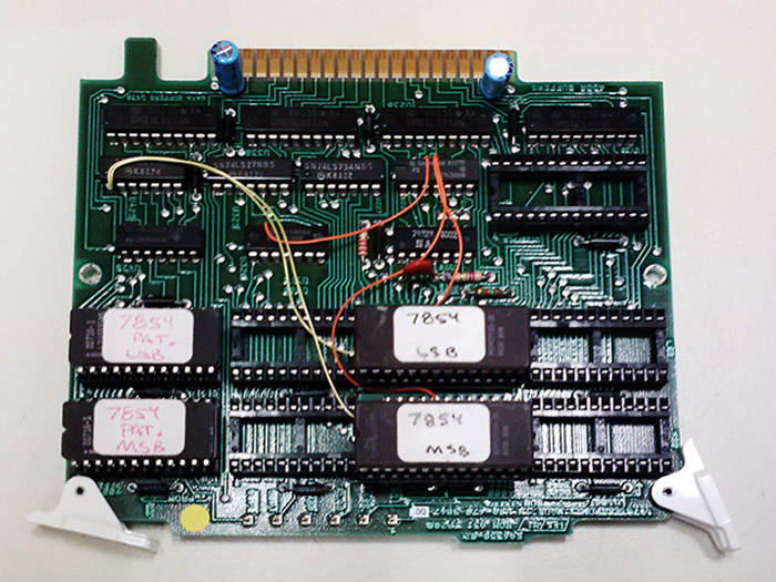
These are the modifications for the 7854 (revised 9/13/16)
- Remove U100 and U200. Program a 27128 EPROM adapter for U200 with MSB data and use U200 location for clearance.
- Remove U110 and U210. Program a 27128 EPROM adapter for U210 LSB data and use U210 location for clearance.
- Wire A13 by connecting both 27128 pin 26 to U425 pin 1.
- Wire new CS. Start by disconnecting the existing CS from U200 and U210 pin 20. We did this by simply not connecting pin 22 in the EPROM adapter (which connects to pin 20 on the PCB) and then flying a new CS wire directly to pin 22 of the EPROM.
- Option 1: Add an unused gate by connecting both 27128 U200 and U210 pin 22 to U225 pin 11. Connect U320 pin 13 to U225 pins 12 and 13.
- Option 2: (We have not implemented this so consider it unverified) Cut and lift U420 pins 9 and 13. They will float high or you can connect these pins to +5V.
- Remove FPLA U120.
- Reprogram a 2716 patch EPROM for U400 with MSB patch data. Reprogram a 2716 patch EPROM for U410 with LSB patch data.