
Here are some photos of various dual beam guns we have at the museum.These are fairly large images to show the detail but you can click on any image to open a PDF where you can zoom in to see more detail.
Just a note about nomenclature. Dual trace refers to a system where two signals are multiplexed on a single gun to create two different beams. In principle, this can be accomplished on any CRT, but in practice there can be bandwidth limitations and only signals with the same time base can be displayed.
Dual beam is used to describe a system that has two completely separate gun assemblies except for a shared horizontal deflection structure. This saves the cost of one horizontal deflection circuit and also can only display signals with the same time base.
Dual guns means there are two completely separate gun assemblies. This requires two sets of drive circuitry but completely unique signals can be displayed.
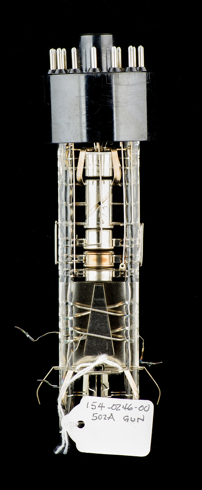
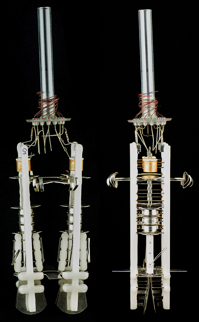
This dual beam gun was used in the 1MHz Type 502A oscilloscope that was in production from 1958 to 1973.
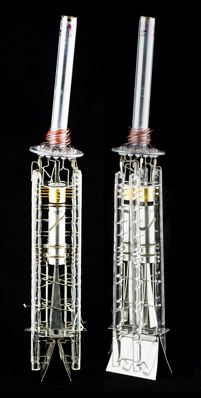
This dual beam gun was used in the 27 MHz Type 551 oscilloscope that was in production from 1958 to 1973.
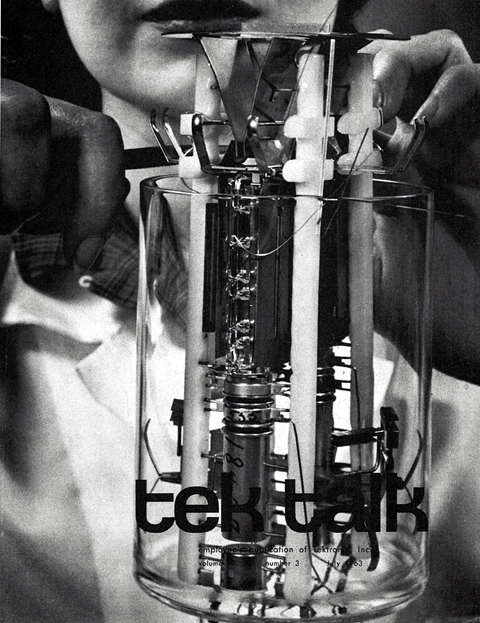
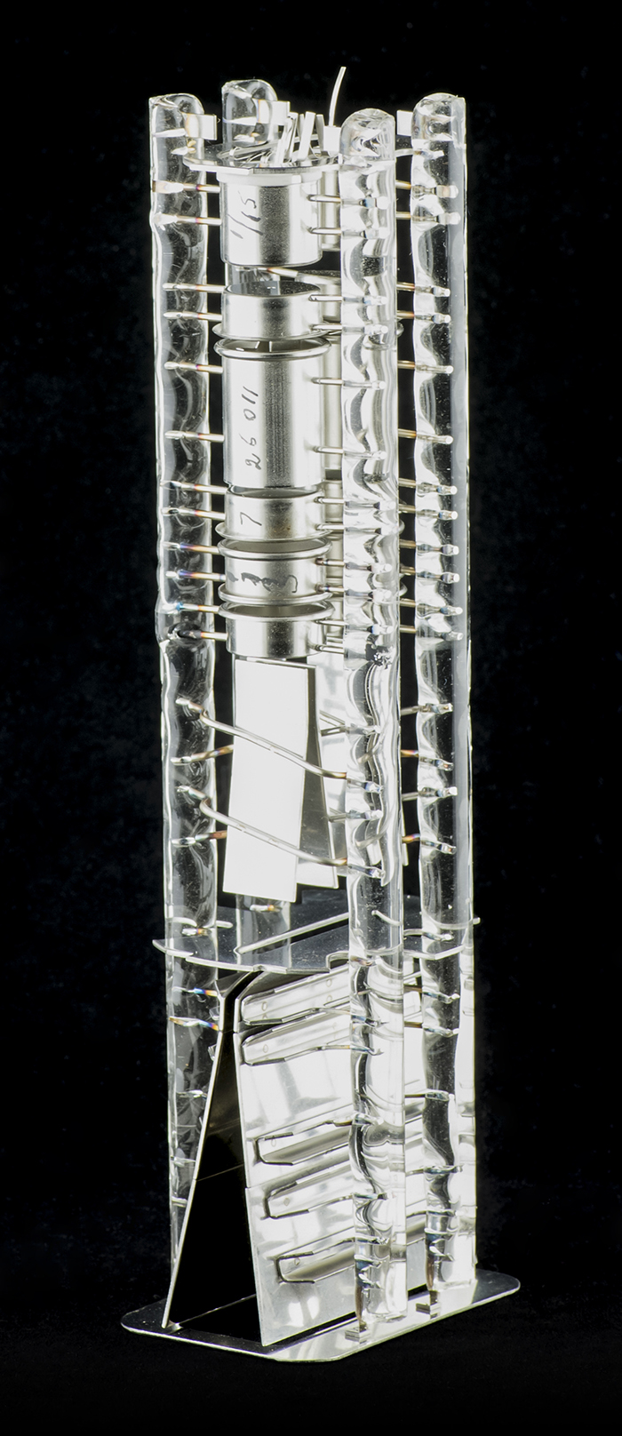
This dual gun was used in the 555 30 MHz oscilloscope that was in production from 1959 to 1970.
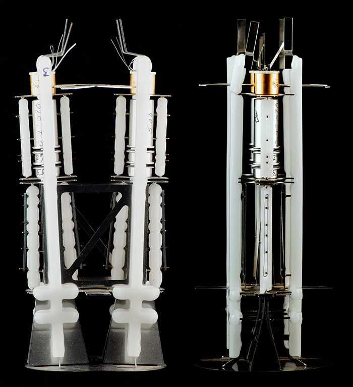
This gun was featured on the cover of the July 1963 issue of TekTalk.
This dual gun was used in the 565 oscilloscope that was in production from 1962 to 1974.
This dual beam gun was used in the 5113 2 MHz storage oscilloscope that was introduced in 1976.
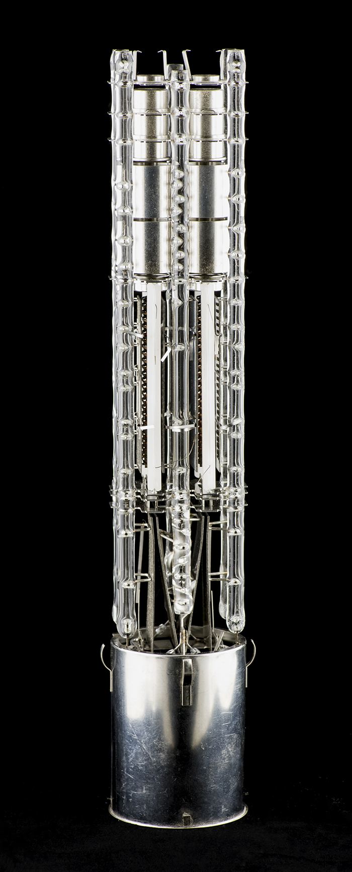
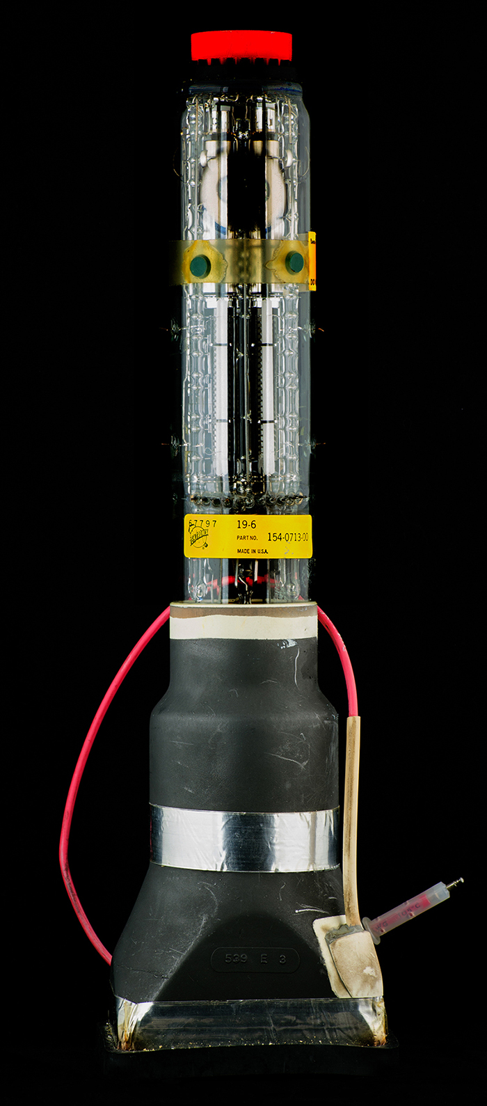
This dual gun was used in the 7844 oscilloscope that was in production from 1974 to 1988. The 7844 achieved a bandwidth of 400 MHz and represents the fastest dual beam oscilloscope Tektronix produced. The gun design is a work of art. Unlike the other dual beam guns which are slightly angled to each other, these guns are parallel. The horizontal deflection plates instead are slightly angled to each other.
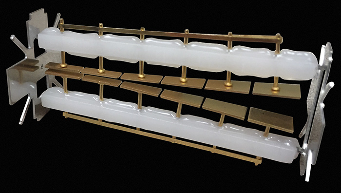
For bandwidth up to and exceeding 50MHz, simple pairs of one-piece deflection plates can be used. These were employed in the 502A and 551 guns shown above. As bandwidth approaches 100MHz the gun designer must reduce the capacitance of the deflection plates. This can be accomplished by segmenting the plate as shown here.
At about 100MHz the speed of the deflection signal in the plates can exceed the velocity of the electron beam as it passes between the plates. Matching the signal and beam velocity optimizes deflection efficiency and can be accommodated by connecting the segmented plates with a conductor that acts as a signal delay line. The delay line is terminated with an external resistor. This was first implemented in the Type 581 and 585 oscilloscopes and is called distributed deflection. Subsequently the function of the deflection plates and delay line was combined to achieve even higher bandwidth called a helical deflector. The 7844 gun incorporated a vertical helical deflector shown here.
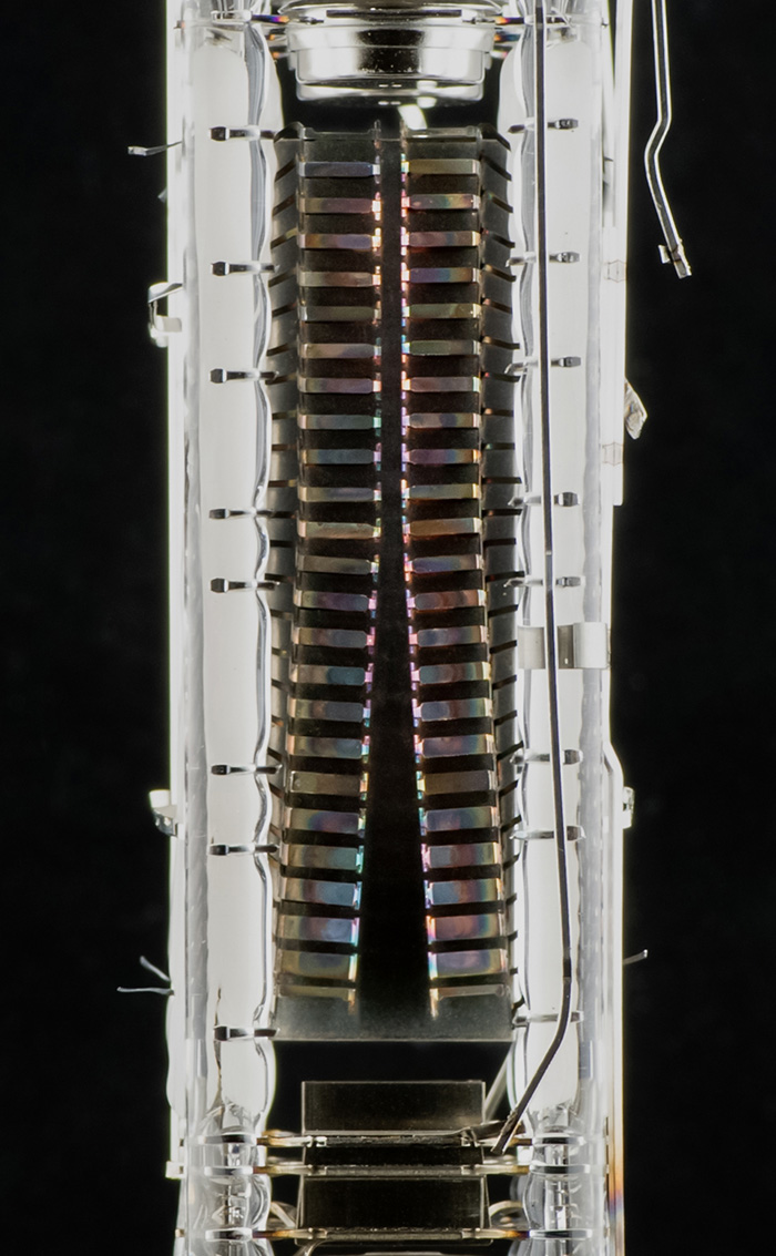
Here is the complete 7844 400 MHz CRT.
We also have an exhibit page for Dual Beam Oscilloscopes and a proposed 552 Dual Beam Oscilloscope.