CRTs used in the Type 519 Oscilloscope
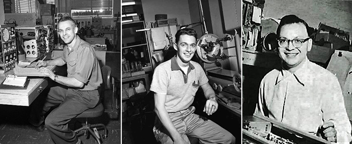
The T519 cathode ray tube used in the 1 GHz Type 519 oscilloscope was one of the most specialized and labor-intensive tubes Tek ever built. CRT development was initiated by John Liedtke in the mid-1950s with the assistance of Bill Brown, who would later manage the Engineering Tube Lab for many years. Egon Elsner was responsible for finishing the tube design and introducing it into manufacturing. John, Bill and Egon, pictured below left to right, worked closely with Cliff Moulton, who was responsible for the overall oscilloscope design.
The CRT had many unique features. Since the primary use for the 519 scope was in the photographic recording of very high-speed transient traces, the only phosphor offered was P11, a blue emitter that offered the highest sensitivity for film capture.
In order to optimize the writing speed, the accelerating (anode) voltage was 24 KV. Precautions were taken to limit x-ray emission from the CRT to safe levels.
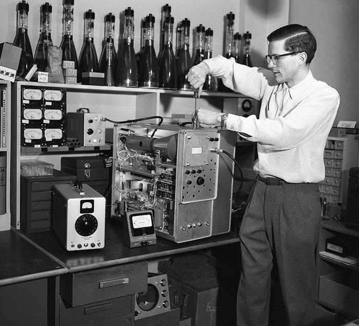
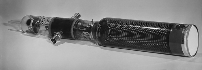
At an overall length of almost 23 inches, it was one of longest CRTs Tektronix ever built. This dimension allowed for maximizing the length of the vertical defector in the electron gun which enhanced the deflection sensitivity. Several prototype CRTs are visible on the shelf behind Cliff Moulton in his laboratory during 519 development. Note the differences in length of these experimental tubes.
Cliff Moulton wrote in a mid-1950's undated Tektronix engineering status report:
"We are continuing development work on the distributed deflection plate CRT. A new model now being built has jig-punched mica cards to support the delay line elements, which are photo-etched from copper or stainless steel.
Two models of this tube may be desirable, one for a combination of high sensitivity, small picture, and highest possible speed; another with a somewhat larger picture at a sacrifice in sensitivity and sweep speed. Both types would probably be adjusted for 24 KV applications."
His prediction regarding two versions of the oscilloscope came to pass. The two versions are described below. Punched mica was used for assembling prototype electron guns because it could be prepared much more quickly and cheaply than production tooling.
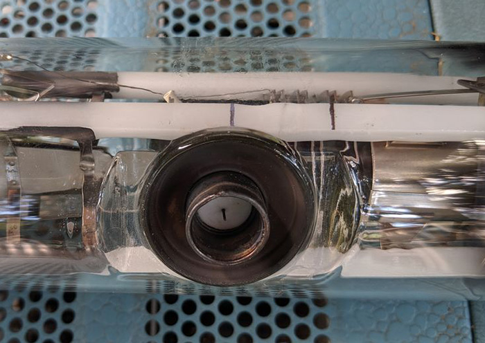
The initial T519 CRT featured a unique distributed vertical deflection design. A solid deflection plate (Item 2) was opposed by a unique stripline deflector (Item 1).
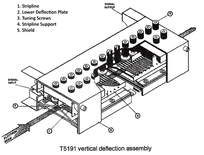
The serpentine deflector required exacting precision and inspection.
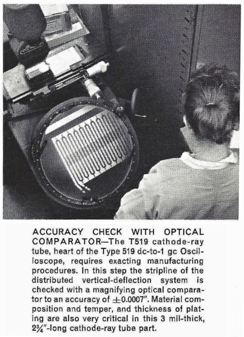
The distributed deflection system improves deflection sensitivity by matching the velocity of the electron beam and speed of the drive signal through the deflection system. The deflection components were built into a box-shaped assembly that was later incorporated into the electron gun. The vertical deflection assembly contained approximately 27 adjustment screws that were used to tune the deflector before final tube assembly by changing the capacitance at each node. This tedious and time-consuming process was performed by select production operators.
Bandwidth for the Type 519 oscilloscope exceeded 1 GHz and the risetime was specified at a nominal 360 picoseconds.
In order to achieve the extreme high frequency response in light of the "stiffness" of the 24 KV anode voltage, the vertical deflection at the screen was limited to two centimeters. This is the smallest vertical scan found in any Tektronix scope. The horizontal deflection was 6 cm. The scanned area on the five-inch diameter tube was small, such that most the phosphor never saw the electron beam. In order to compensate somewhat for the small scan area, the electron beam diameter was minimized in the gun design. Typical Tektronix scope CRT spot size was 0.010 to 0.015-inches, but in the 519 it was specified to be 0.004-inches which provided a very crisp trace.
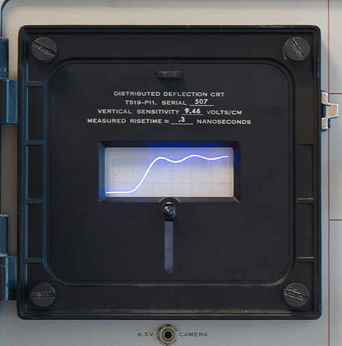
Each CRT was individually tested for risetime and deflection sensitivity (typically around 350 picoseconds and 10V/Div, respectively). Because the instrument did not have a vertical amplifier, these results were written on the bezel of the oscilloscope. This matching of CRTs and instruments complicated field replacement of a CRT and prompted use of an additional label with this information that was attached to magnetic shield. A December 7, 1967 entry into "Maintenance Notes" from Charles (Sandy) Sandford described this update.
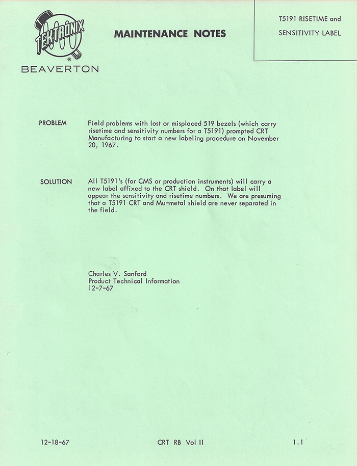
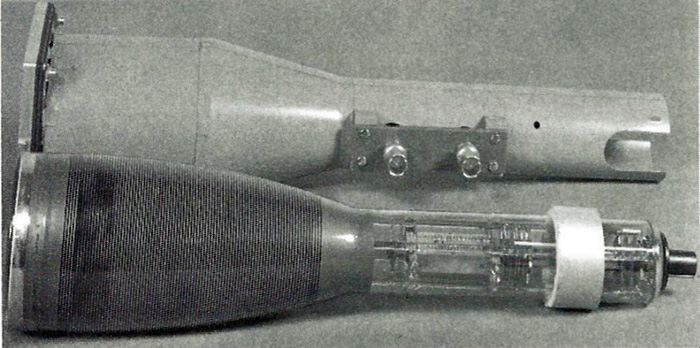
In use, the CRT was enclosed in a close-fitting mu-metal magnetic shield. This was fitted to the tube prior to accurate matching of the coax to the CRT neckpins and measurement of risetime. The T519 CRT and shield are shown in this photo below from the Tektronix catalog.
Replacement CRTs were listed in the catalog for $1,000 ($9,400 in 2021$).
During the early 1960s, the US weapons labs, e.g. Lawrence Livermore National Laboratory, requested a higher-performing version of the CRT design capable of higher bandwidth and faster risetime. The special-order variant scope incorporating a new CRT, described in the mid-1963 to mid-1964 Tektronix catalog (Number 22), was eventually called the 519C. It was only mentioned briefly and only in that particular catalog. The risetime for this new tube, designated the T5192, estimated as 130 picoseconds and the bandwidth specified as 3.0 GHz.
DC-to-3 GIGACYCLE OSCILLOSCOPE
This modified Type 519 Oscilloscope incorporates a coaxial-deflection CRT to achieve a risetime of 0.13 nsec, corresponding to a 3000-MC bandwidth. Deflection factor is approximately 180v/cm. Usable viewing area is 2x4 cm. Consult your Field Engineer to learn about the advantages, limitations, and delivery time of this or other modified instruments.
The relatedly low deflection sensitivity - 180V/cm - indicates the customers had plenty of signal. Another indicator: The catalogs offered 10:1, 125 ohm attenuators for the Type 519. In a 1963 report to the Tektronix Board of Directors the T5192 was described:
T5192. A CRT which fits the 519 scope that features a coaxial straighthru section for the vertical deflector. Risetime is on the order of 120 picoseconds (bandwidth about 3Gc). Horizontal scan has been sacrificed for horizontal sensitivity so that the sweep can go at double the normal rate or 1ns/cm which is more compatible with the faster risetime. This tube type was announced publicly in February 1963.
The original T519 was renamed the T5191 after the T5192 was introduced. No detailed documentation for the T5192 deflection system survives, but a single, 0.020-inch wire is described in the February 1, 1963 issue of TekWeek as replacing the serpentine vertical deflector assembly. Special GenRad 125 ohm connectors were used for signal input and termination to the deflection system. The connectors were incorporated into the CRT neck via a so-called housekeeper glass to metal seal developed by Bill Brown.
The Type 519 oscilloscope last appeared in the 1973 Tektronix Catalog as a “limited demand” product. At the time the new Type 7904 scope was the recommended replacement using the 7A21N plugin. That configuration had the same bandwidth specification of 1 GHz and risetime of 360 picoseconds as the 519, but much improved vertical sensitivity.
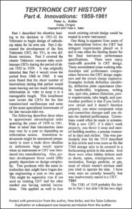
Pete Keller’s article on early Tektronix CRTs includes the 519. Click on the image to view the PDF.
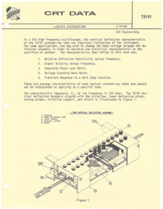
In 1966 George Hashizume prepared a detailed analysis of the type 519 performance. Click on the image to view the PDF.
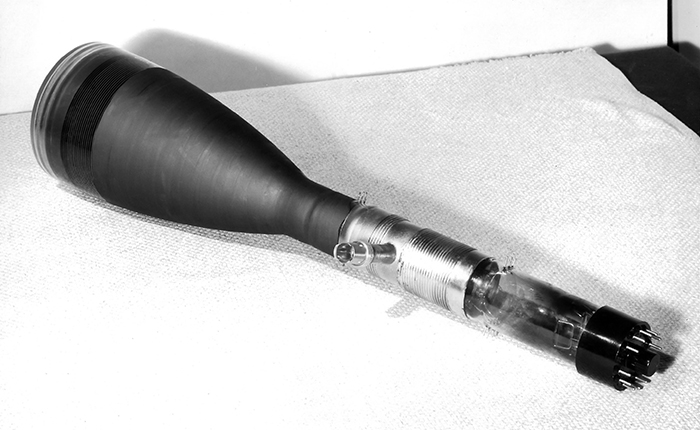
Bill Brown provided two photos of early T519 prototype CRTs with preliminary vertical deflection connectors.
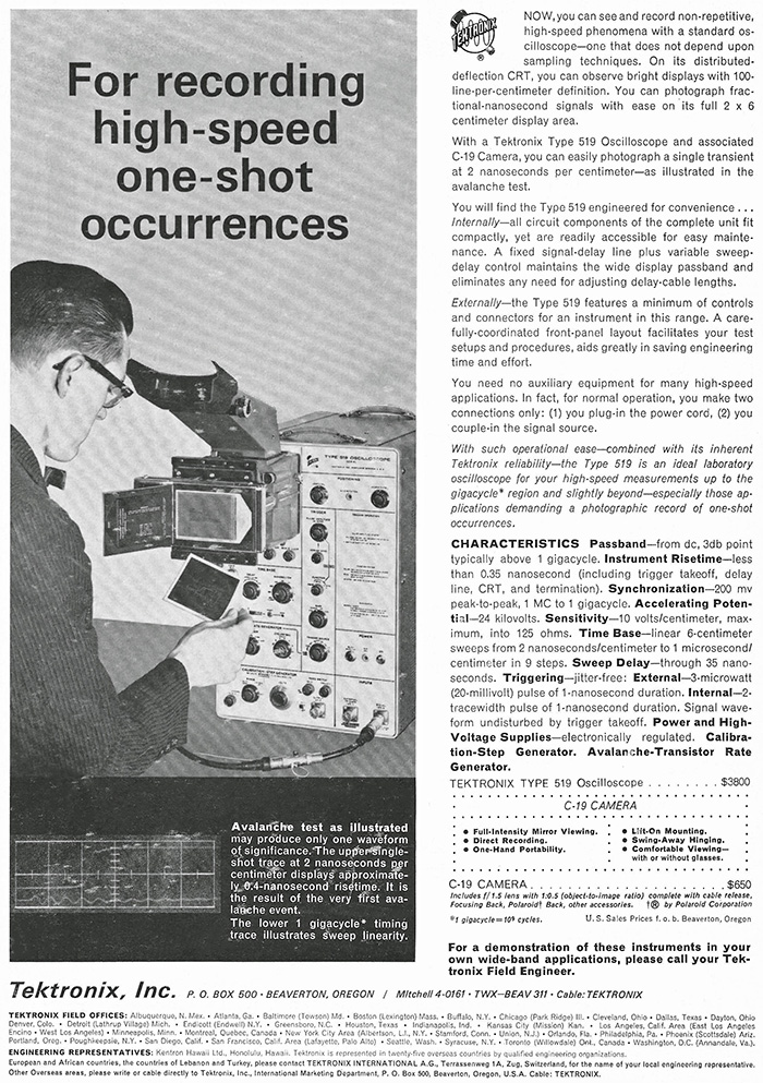
This ad for the 519 appeared in the January 1962 Review of Scientific Instruments.