by: Donald Chitwood
This story was written and posted on the usenet group tek.rumor by Don on November 19, 1996.
I think I'm one of the few people remaining at Tek who worked on that project. For those who want one person's memory of its history, here it goes.
I worked for Bill Beran in building 50 at the time where the cathode was developed. Bill and Kevin Considine, the microscope project leader, both worked for Harry Anderton.
The scanning electron microscope was strongly supported by Howard Vollum. As others have pointed out here, it was Tektronix second fling with electron microscopy. My involvement initially was the development of the cathode, a field emission cathode with a few "new" tricks to give it a very bright electron source which was the heart of Tektronix design concept. Eventually, I became the caretaker of the remaining operational instrument, in part because no one else knew how to make the cathodes. Cathodes died horrible deaths because of unsolved electronic glitches that would, for example, open the hi-vac valve to atmosphere during operation. Failures like this usually took out lots of electronics, particularly the 3 or 4 high voltage power supplies that powered the electron gun and various parts in the vacuum chamber. Circuit board attrition was quite high; we even had some made and stuffed in order to keep running. We made lots of progress as we fought with and l earned from each failure mode, and eventually had a pretty stable instrument. For about 10 years we offered its use to others throughout the company and among the academic community as a service.
Of course, the usual parade interesting specimens, bugs, hairs, skin flecks, were. My most fun sample was medical. One night, I passed a kidney stone. I wanted the doctor to have all the information he possibly could the next day, so I put the stone in the microscope and took several pictures. They were quite remarkable photos. My doctor had never seen kidney stone pictures like them and took them with him to OHSU to show the class he taught.
I managed to convince my bosses to keep the instrument alive over the years because it was so incredibly useful and capable. For example, it had an enormous depth of field because of the unique electron optic design by Mel Balsiger , George Hashizume , and others. The sample chamber could accommodate very large samples. It was easy to use and had that stunning, tv-quality, real-time picture on the screen. Granted, field emitter cathodes are inherently noisy, but we found ways to accommodate that so it wasn't an issue.
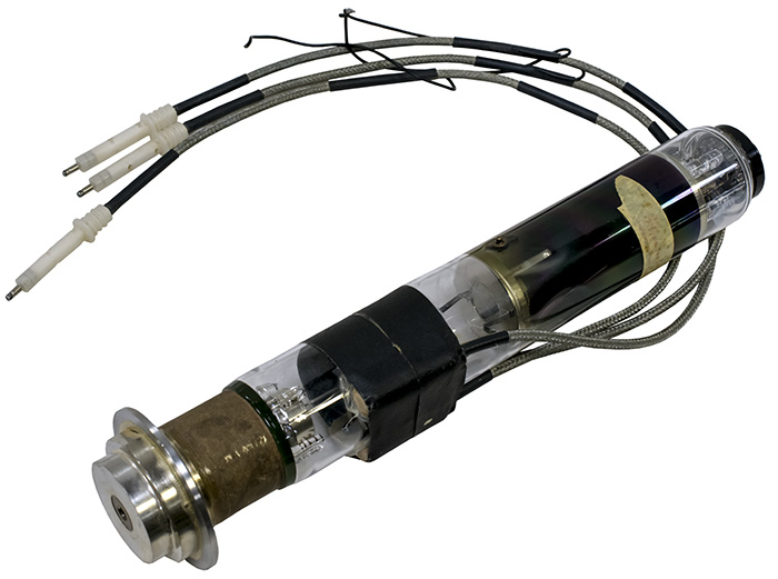
When the project was stopped in 1974, manufacturing had begun and parts inventory was building up. The field emitter cathode was contained in a CRT-style gun assembly which contained its own sublimation high-vacuum pump and a puncturable hermetic diaphragm that allowed manufacture of the gun as a separate unit. The guns were being produced in bldg. 48 with a surprisingly high yield.
To my memory, 3 instruments were built that lasted for any time. One was an "A" phase prototype, the other two were improved "B" phasers, essentially pre-production units. The A phase unit was put in storage for parts, and I chose the best of the B phase units to keep running. The other B phase unit was given to the then Oregon Graduate Center, in part because Lynn Swanson, who was our consultant for field emission work, taught there. When I finally gave up on maintaining the remaining instrument, I think Jon Sonneborn in CRT was interested in having it. The last I saw of it was in the basement of building 46, 4 or 5 years ago. I'm sure someone got it at the country store and wondered what the hell they had.
The driving idea behind this microscope was to create a real-time view of a sample with tv image quality. The field emission cathode made this possible. A favorite demo was to put a wind-up wristwatch mechanism in the chamber and watch the escapement mechanism work. You could zoom in and watch bearing surfaces wear. The instrument itself was physically small, about the size of a normal office desk.
There were conscious design / marketing tradeoffs. For one, resolution was low, on the order of 300-400 angstroms on the first model (the only model, as it turned out; higher resolution designs were on the drawing board.) This gave a fairly good image at 10k magnification. Magnification ranged from 10X to 10K, with a 3X zoom capability at any setting. It was aimed at a nitch market, to sell for ~$20k . The nitch was the realm between the upper limits of light microscopy and the low to mid-magnification of high-powered electron microscopes. The incredible depth of field made sample navigation very easy and intuitive. It was also very user friendly, at least in concept. The only "tweaks" in common with a high-power electron microscope were astigmatism. Everything else was almost tv-like, very direct and simple. Vacuum system operation was by a single button and completely automatic (an obvious and good idea, but poorly implemented with often catastrophic results.) There were also plans for a multitude of sample stages which even today aren’t common. For example, sample heaters for watching melting processes; metallurgical pull testing so metal stress and failures could be studied. Ah, the dreams!
As I said earlier, the field emitter cathode was the heart of the instrument. To make one, a 5-mil diameter single crystal tungsten wire, made by Ken Stinger, was welded to a hairpin-shaped tungsten filament. The wire was partially immersed in a sodium hydroxide solution and electrochemically etched to a fine point. The radius of the etched point determined the operating voltage of the cathode: the larger the radius, the higher the voltage. My challenge was to control the etching process so that cathodes always operated within the specified voltage range of the power supplies.
The field emitter cathode was then precisely mounted in the electron gun. When the gun was pumped down and activated, the tip of the cathode was then "formed" into a specific crystallographic shape by a process we called "flipping". What this did was to change the electron emission pattern of the tip from four rather weak, off-axis electron beams emitted from the cubic corners of the single crystal into a single, narrow and powerful beam directly on axis. During the "flipping" process, electron emission would increase by at least 3 orders of magnitude. It was almost a religious experience to watch it on a phosphor screen.
The secret to the process was the admission of small quantities of molecular oxygen to the gun vacuum. The oxygen allowed the tungsten atoms at the tip to reorient themselves under the influence of a high electric field and heat from the filament. Before flipping, the tip was physically cubic at the tip, with the center of one face of the cube being perpendicular to the axis of the wire . During flipping, atoms migrated into a pyramid shape where the electrons were pulled out of the apex of the pyramid with great efficiency. The pyramid shape was stable under certain conditions, so "flipping" only needed to be done once.
When the project was cancelled, we were told it was due to several factors. 1) there was a recession in the early 70' s which finally got to Tektronix. 2) Plans were a foot to build the site at Wilsonville and there wasn't enough capital to finance both projects, particularly since the microscope project was speculative. In hindsight, I can clearly see the many problems with the design and how far from market it really was. However, to this day, I think it could have been done well with what was being learned at the time had it been given the chance. The big success was learning how to make and operate a field emission cathode reliably. There was nothing available at the time anywhere close to it in price/performance.
It remains for me one of the great examples of the benefit of corporate internal diversity. The wide range of processes, expertise, and capabilities that Tektronix had under one roof made it possible to conceive and produce something like that instrument. What a delight to have been part of it!
The museum has a SEM cathode emitter on display.