In June of 1949 Tektronix developed a wide-band high speed oscilloscope under contract to the Air Materiel Command for $50,000. This oscilloscope pushed the limits of high speed analog design using distributed amplifiers and had a total of 108 vacuum tubes. This report, issued by Howard Vollum and Dick Rhiger on May 31, 1950, covers the final development, construction, and performance testing of the oscilloscope. Click on the image to view the PDF.
Following this research contract was the development of the Type 517 oscilloscope which achieved a performance of 50 MHz. The 517 was designed by the first three Tektronix engineers - Howard Vollum, Logan Belleville and Dick Rhiger. Frank Hood, employee #32, recalled the work on the 517 in his Tektronix, The Early Days story.
"A lot of progress was made in 1949 and 1950. Work was well underway by Logan Belleville, Dick Rhiger and Howard on the high speed scope, the 517. This used some brand new circuitry, distributed (or chain) amplifiers, using 16 to 20 tubes in each stage to get the power needed to handle the high frequencies. Our best prediction at that time was that there were only about 30 to 50 people in the whole world who had need of a scope with 60 to 100 megacycle bandwidth. As it turned out, when we brought out a higher speed scope, people were able to design equipment of greater bandwidth and needed even faster measuring instruments. The cycle was regenerative. Having faster, more accurate measuring tools created a demand for even more measuring tools. We eventually sold several thousand of this instrument."
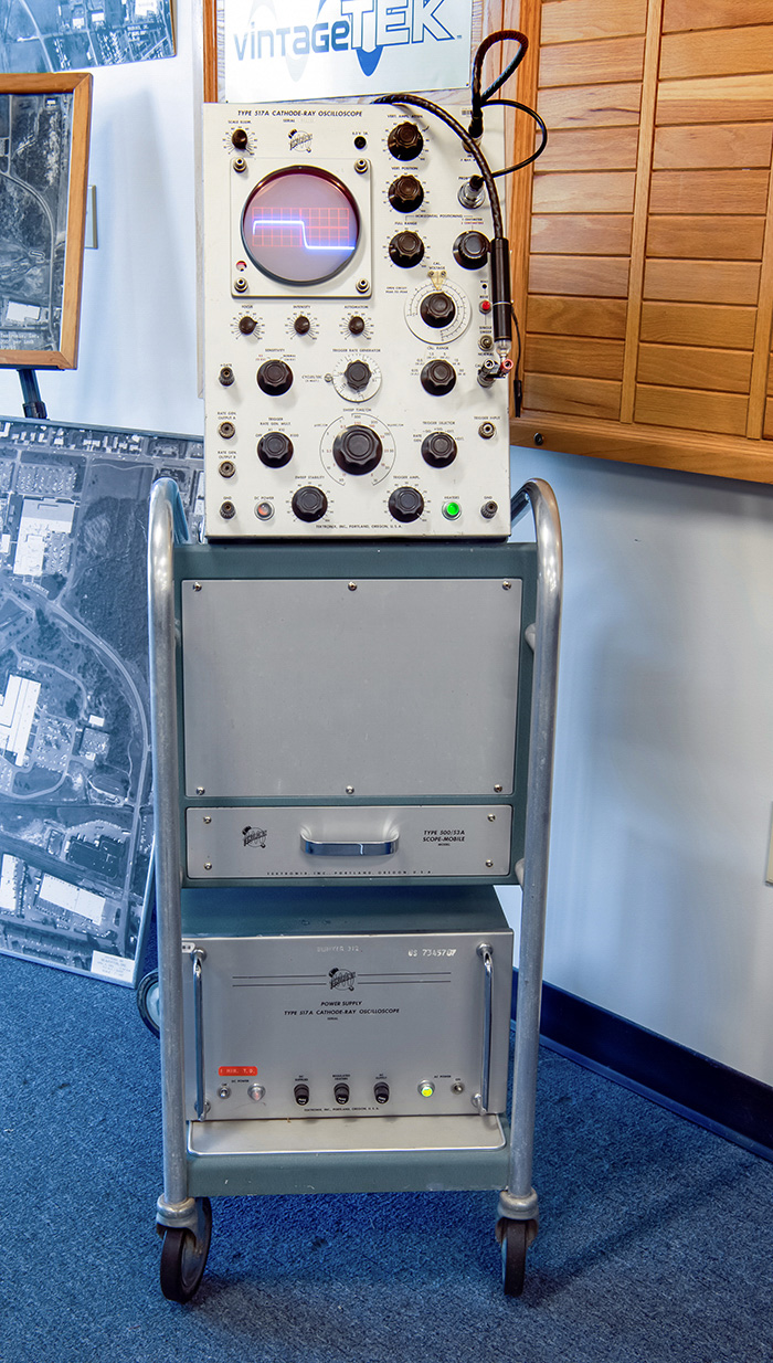
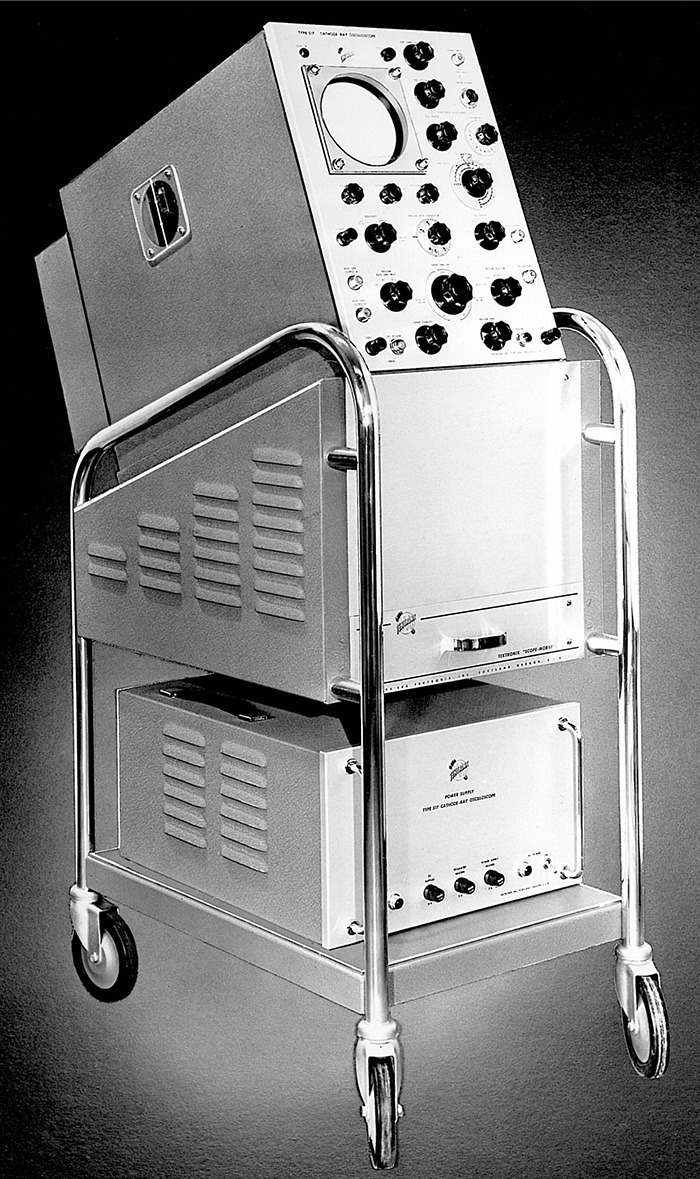
The Type 517 was not a petite unit. The innovative distributed amplifier design required many more amplifier tubes than a conventional scope (a total of 130 vacuum tubes) and power consumption was 1250W. Most all 517s were mounted on a cart, providing some amount of portability for the indicator unit and the separate power supply. Total weight for the oscilloscope was 175 lbs.
Perhaps it should be noted that when Tektronix’ first product, the 511, was introduced in 1947, among its attributes was the dramatic reduction in weight (initially, 65 lbs, later 50 lbs) it offered over its nearest competitor, the DuMont Type 248. The Dumont scope also utilized a separate power supply and weighed an even more cumbersome 197 lbs.
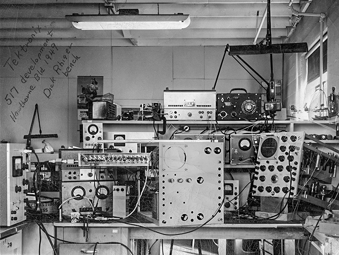
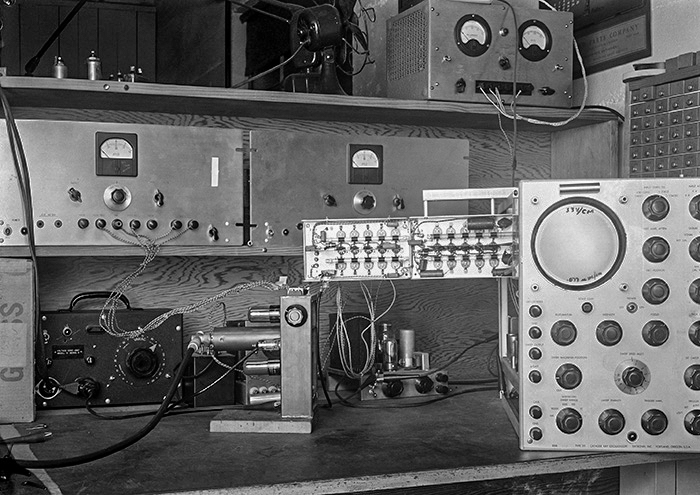
These two photos show the 517 under development on the bench of Dick Rhiger at the Hawthorne plant.
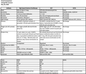
This comparison chart shows the differences between the high speed, 517, and 517A oscilloscopes. Click on the image to view the PDF.
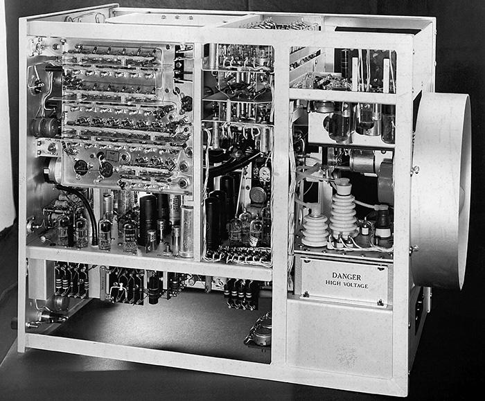
These two photos of the 517 come from the 1952 Tektronix Photo Album.
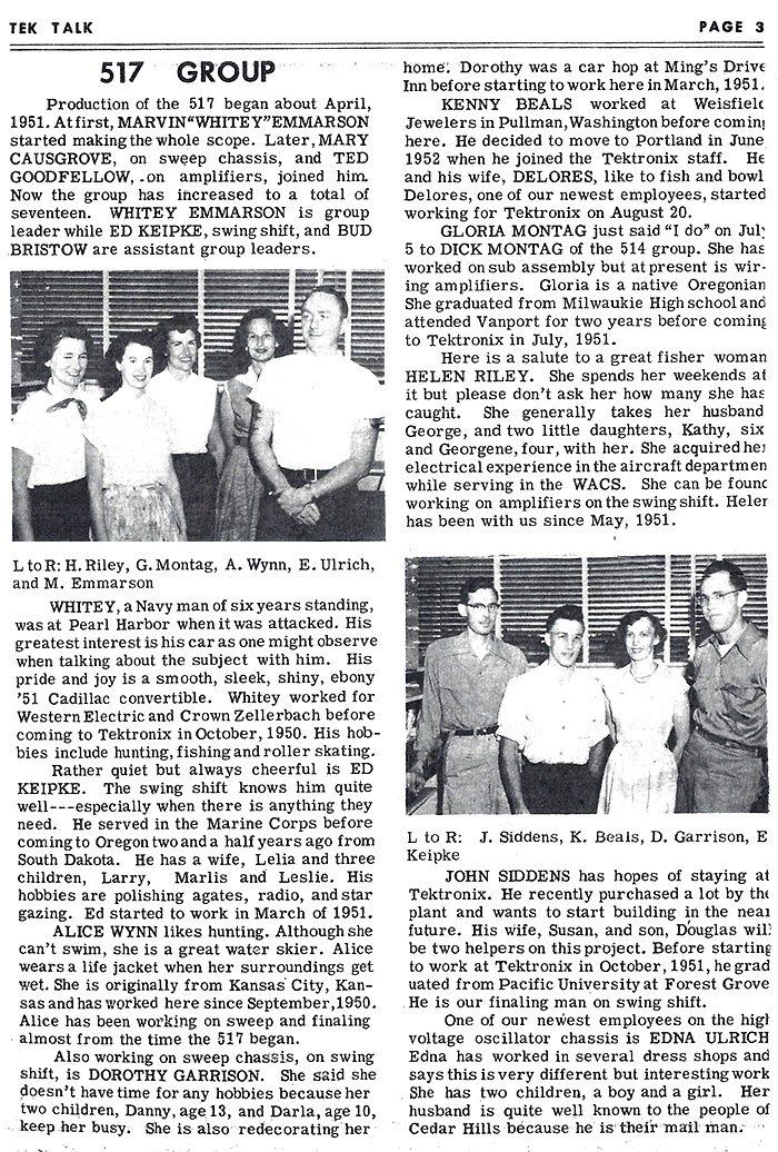
This September 1952 Tek Talk describes how the manufacturing group grew from one person, Marvin “Whitey” Emmarson. to adding Mary Causgrove and Ted Goodfellow to a group of seventeen. Ted later created Tektronix proprietary ceramic strips.
This photo shows Dick Rhiger with the 517 oscilloscope.
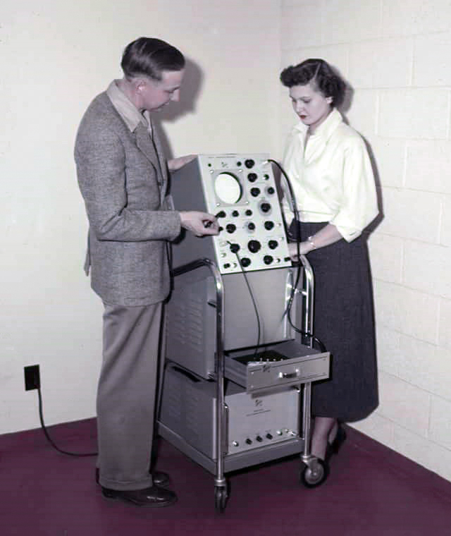
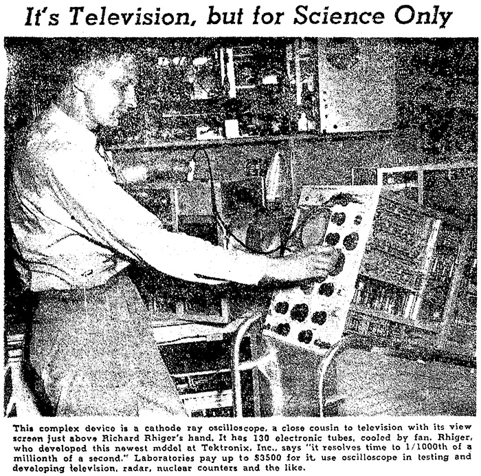
This April 9, 1951 Oregonian article features Dick Rhiger with the Type 517.
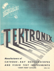
The 517 first appeared in the August 1951 “Short Form” Tektronix catalog for $3,500, the equivalent of over $35,000 today. Click on the image to view the PDF.
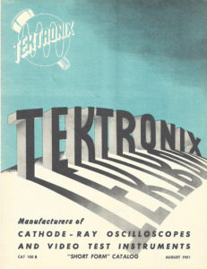
The 517 also appeared in an updated August 1951 “Short Form” Tektronix catalog. Click on the image to view the PDF.
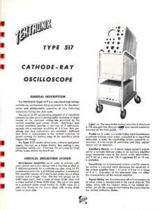
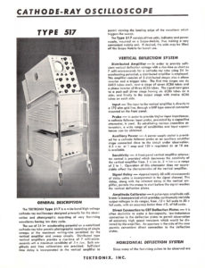
It also appeared in the August 1951 Tektronix Catalog. Click on the image to view the PDF.
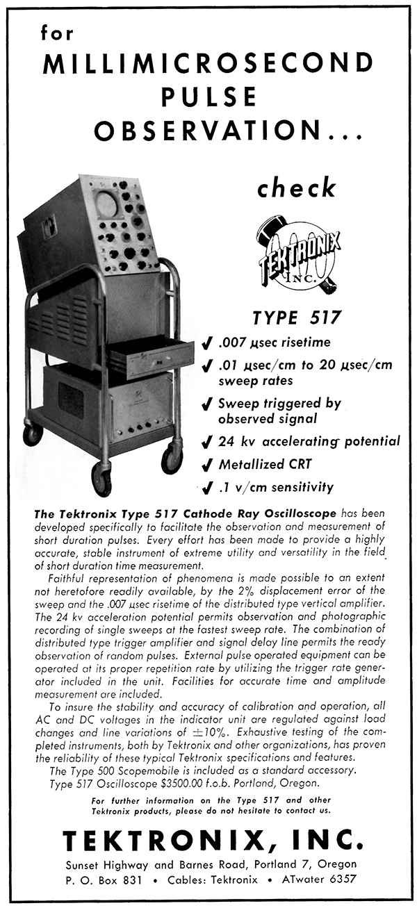
The first advertisement for the Type 517 was in September 1951.
This 517 excerpt is from the 1952 Tektronix catalog. Click on the image to view the PDF.
The 517 was in production from 1951 to 1955 and used a DuMont 5XP11 CRT in the first 825 instruments. Quality and supply problems with this and other CRTs from DuMont and RCA were a significant factor in Howard Vollum’s 1951 decision make their own CRTs.
Tektronix designed and built T54P11H CRTs which were used in newly-designated 517A scopes for the rest of the product’s life. These tubes used Tek’s unique helical anode accelerator that provided improved electron-beam spot performance compared to the DuMont CRT.
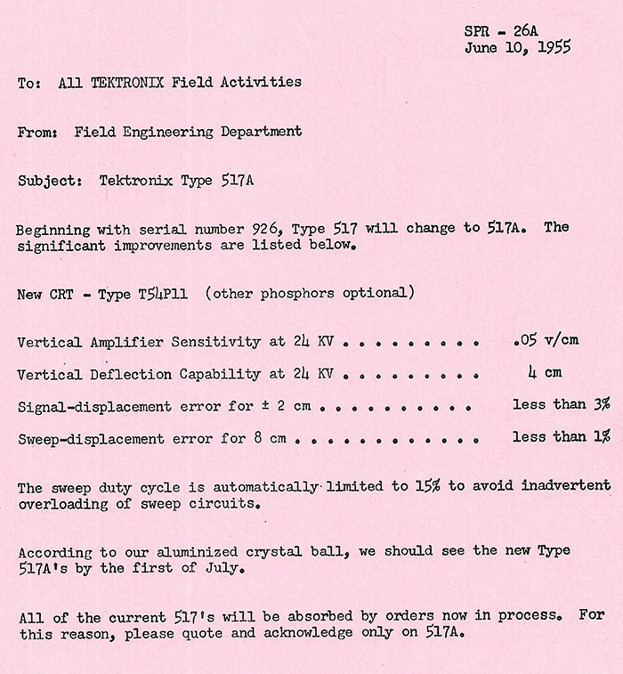
This June 10, 1955 document announces the change and “significant improvements” of the 517A. The reference of the "aluminized crystal ball" was an inside joke referring to the CRT with its reflective, thin-film aluminum coating on the gun side of the phosphor.
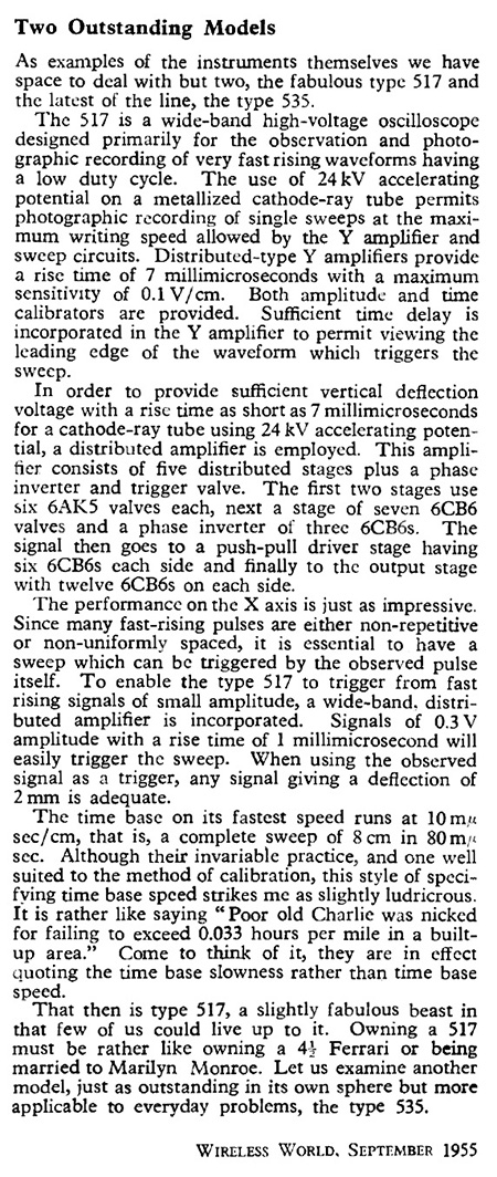
In 1955 Tektronix had a big fan in the person of A.J. Reynolds of Livingston Labs in the U.K. This excerpt from his September 1955 Wireless World article contains glowing praise for Tektronix in general and the Type 517 and 535 scopes in particular. He compared owning a 517 to having a Ferrari or being married to Marilyn Monroe…!
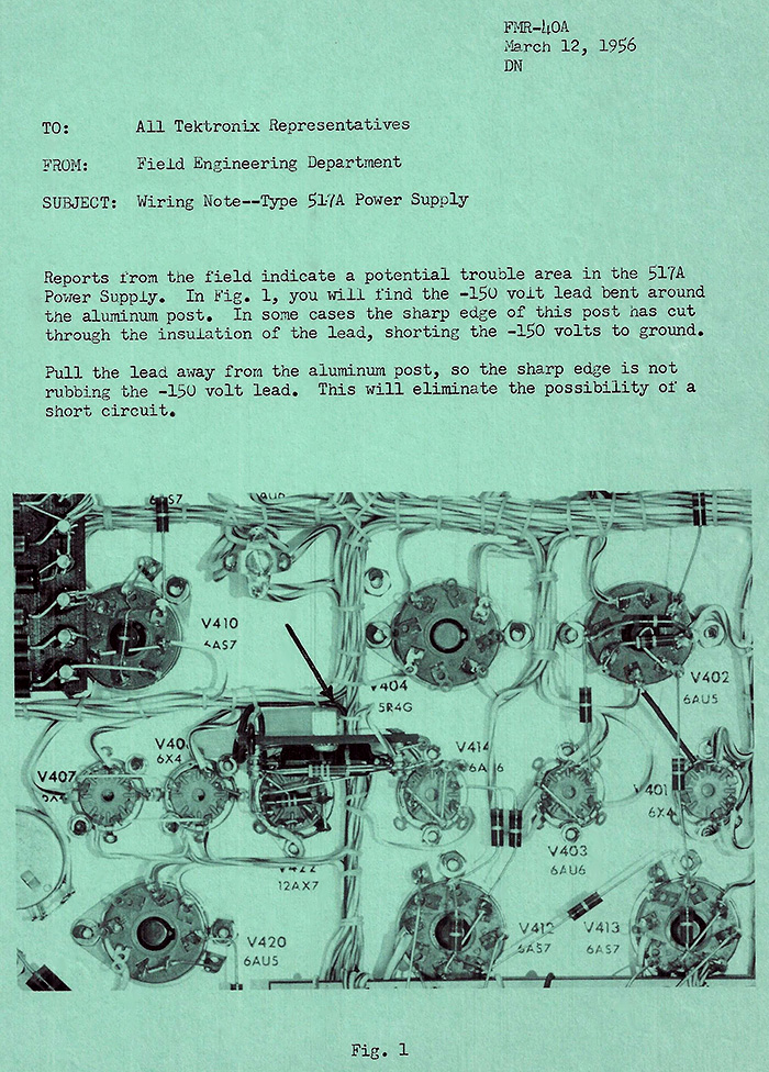
This 1956 document describes a change in wire routing for improved reliability of the 517A .
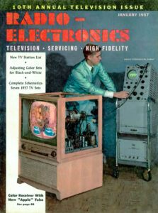
This January 1957 issue of Radio-Electronics features a 517 on the cover. There is no more information or mention in the issue.
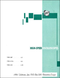
This 1961 High Speed Oscilloscopes brochure features the 507, 517A and the 519. Click on the image to view the PDF.
The 517/517A enjoyed a 14-year production life until replaced by the 547. It offered the highest performance available for observation of extremely short pulses in a commercial oscilloscope for many years. This was coveted by high energy physicists and cold war weapons researchers. A custom version, the 517RS, was offered for these applications. It was not uncommon for these instruments to be destroyed or contaminated during nuclear weapons testing. Units returned to Beaverton for refurbishment were sometimes found to have bent frames, broken tubes and evidence that the aluminum parts had been exposed to salt water – in addition to measurable radioactivity. In fact, checking a 517 with a Geiger counter became a standard practice when these oscilloscopes entered the plant. A special cleaning process was developed to remove contamination and details were available from Tektronix Field Engineers.
The museum has been seeking a 517 for some time and museum founder Stan Griffiths donated a "parts unit" which was in pretty rough shape. Our volunteers worked to restore this instrument. Over 50 electrolytic capacitors were replaced in the vertical distributed deflection amplifiers alone and the instrument received a thorough cleaning.
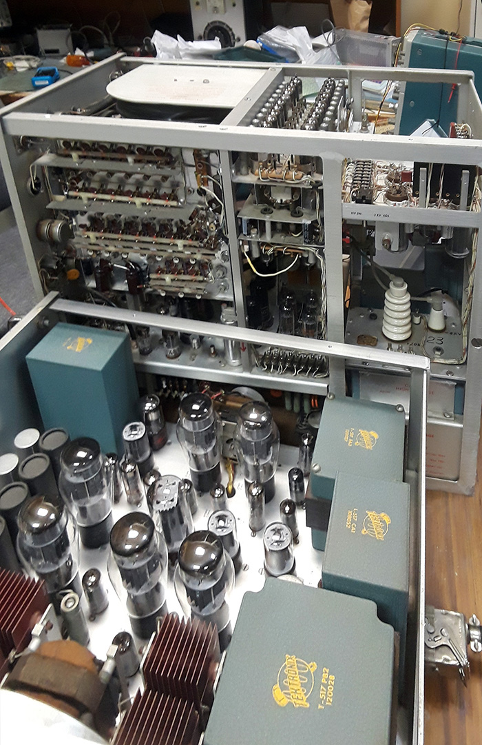
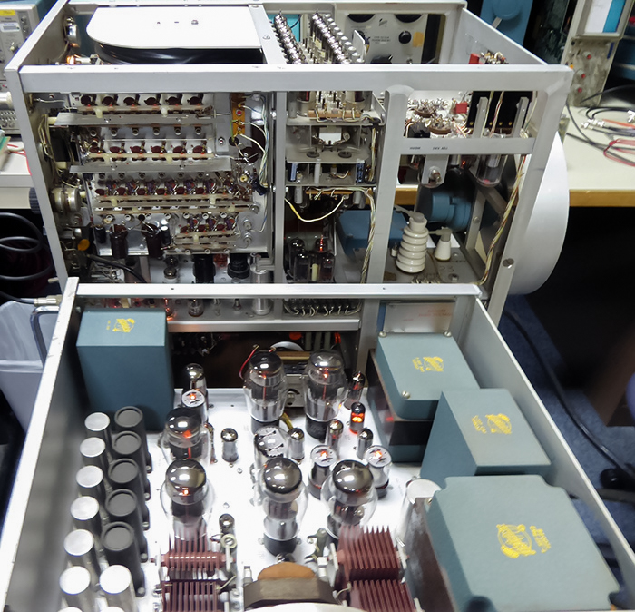
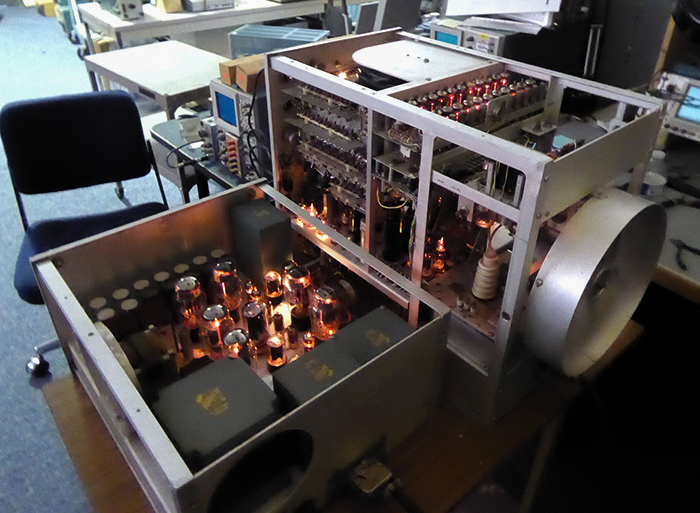
After cleaning and verifying all the power supplies, the 517 is first powered on and the glow of the 130 tubes can be seen (and felt).
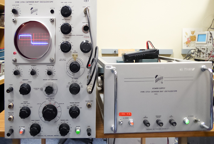
The result result of this effort was first light likely in decades. We do not know the existence of any other operational 517 oscilloscope.
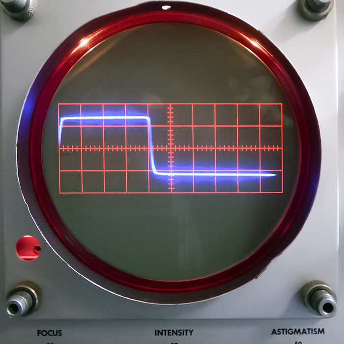
This is the trace of the internal calibrator.
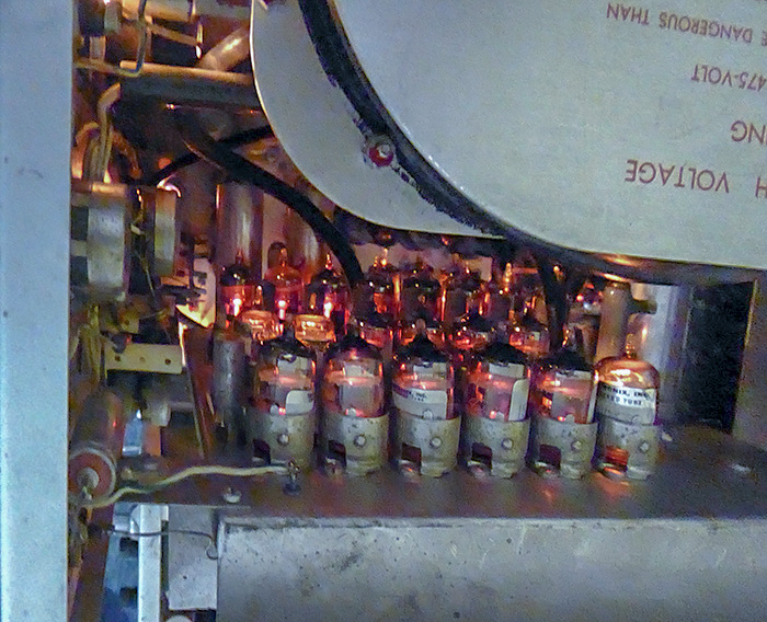
In a semi-darkened room the glow of 130 tubes is impressive.
Our 517 is on display up front in the museum.