December 2017 Update
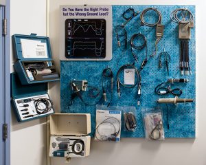
We are continuing to catalog new donations of equipment and documentation at the museum. Although the showroom and classroom are nearly full, we recently added a display of some of our analog and digital probes.
This month we bring you some history on the Television Products group. Effective measurement of television signals requires features not found in general purpose oscilloscopes. Television signals spend about 80% of the time conveying variable content, leaving only the remainder of the time to convey information about reference levels and the times at which they can be sampled.
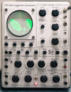
The 524 was designed by Cliff Moulton, who had designed the features that, when added to the 514, turned it into the 524. This circuitry identifies the timing information irrespective of the video content. Other features of the video signal were blanking pulses that delineated the time of video versus no video. In the 1950s, this was all done using analog circuitry dependent on resistors, capacitors and vacuum tubes, not a very stable setup. Accordingly, the 524 also featured time markers generated by relatively stable L-C ringing circuits to ease the measurement of sync and blanking pulse widths. The museum has a 524AD on display.
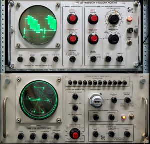
TV waveform monitors are specialized oscilloscopes used for monitoring TV signals in studios and transmitters. The 525 was the first waveform monitor that Tek produced, first appearing in the spring 1955 short-form catalog. In 1955, the National Television Standards Committee (NTSC) issued a standard for a compatible color television system, an enhancement of the earlier 525 line monochrome system. In late 1956, Charles Rhodes, working with Ron Olson, started work on an oscilloscope called the 526 vectorscope. Its primary display mode was an X-Y display of the orthogonal components conveying color information about each point in the raster. So the signal can be represented as containing three components, Y, R-Y, and B-Y. Sales of the 526 began at a brisk pace in 1959, but began to taper off as customers began to witness the poor the performance and stability of the first-generation color equipment.
As color equipment manufacturers used the 526 to diagnose their deficiencies, performance improved, color became more acceptable and sales of receivers, studio equipment and program content rapidly increased. Executives working in the TV industry stated that the vectorscope hastened the introduction of color television by at least three years. The museum has a 525 waveform monitor and a 526 vectorscope on display.
Tek began building glass CRTs with rectangular envelopes in 1959. They were used in the 527 and rack mount RM527 waveform monitors that first appeared in the 1961 catalog. The 527 and RM527 were also the first waveform monitors to be offered in two physical configurations, a 5.25" high rack mount and a 10.5" half-rack wide cabinet model, popular because it enabled two camera control units to be housed in the same rack, useful for operating in cramped spaces. The first 527s were delivered for the new KNXT-TV CBS Technical Operating center opening in Los Angeles in early 1960.
It wasn't until well after the 527 appeared on the market that a mostly solid-state waveform monitor could be built. The need to use test signals buried in the vertical blanking interval necessitated attention to CRT and amplifier design in order to achieve the needed writing speed performance. The 529 replaced the 527 and employed a transistor-vacuum tube hybrid technique to achieve the needed voltage swing performance using a monoaccelerator CRT. The 529 and R529 enjoyed a product lifetime of more than 11 years. The museum has a 529 waveform monitor and 520A vectorscope on display.
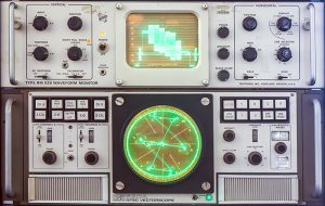
The 520 spawned the 521 which was compatible with the emerging European PAL system. While the 521 was under development there was one major obstacle - no test signal! An engineer volunteered to design a PAL "test fixture" signal generator using the new digital ICs of the era which generated PAL color bars, linearity staircase and convergence signals.
In order to demonstrate the 521, the "test fixture" was the only source Field Engineers used. While demonstrating the 521, customers naturally asked about the "test fixture". Soon management understood that Tektronix could enter a new product area. The PAL "test fixture" became the 141 and the 140 NTSC version quickly followed.
In the days before digital and satellites, TV was conveyed across the nation over microwave links averaging 50 or 60 miles in length. 60 analog hops meant that a relatively small amount of signal degradation could cascade into a serious problem and bad links needed to be identified. Design of hardware that could detect 2% of an analog problem was a big challenge. However, taking on and solving that challenge was the big reason that the market share enjoyed by the TV Division was so large.
More information can be found on the Television Products exhibit page.
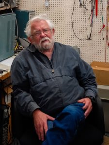
We would like to highlight another volunteer this month, Phil Crosby. Phil got his ham ticket W7PYX, when he was 10. His sister said her friend's father worked at Tektronix and just lived up the street. Phil visited him and he took a shine to him and setup an interview for a Summer position in 1957. Phil worked that summer when he was just 16 years of age. In 1959 Phil accepted a job with Charlie Rhodes in the TV group, where he worked until 1968, leading some TV projects and helping with the 556. Phil was then "drafted" into the 7K group in 1968 where he worked until 1971 doing the 7503 and 7403, and project manager on some plug-in projects. Phil went back to the TV group in 1971, where he "advised" a number of projects and developed an 8 bit A/D video converter, which was later sold as a product and enabled the 1980 Video Measurement System for digital capture and measurement of video signals. In 1983 Phil moved to Tek Labs to pursue a number of projects including A/D performance measurement, optical streak capture, a format converter for evaluating HDTV proposals and then MPEG hardware. Phil retired from Tektronix in 1999 and volunteers as a restoration engineer at the museum. He is also the Secretary on the vintageTEK board. There is a February 15, 1985 TekWeek article on Chief Engineer Phil Crosby on our Chief Engineers page.
We continue to enhance the vintageTEK museum website. The home page has links for newly added material.
Please stop by in person if you are in the area for a tour of the museum. If you have time to contribute, we'd love to have you as a volunteer. Stop by to discuss opportunities and needs.

