The first Tektronix oscilloscopes were produced at a time when printed circuit boards were not in use. Many electronic products made use of point-to-point wiring between components and this was inherently tedious to fabricate, difficult to troubleshoot and aesthetically dissatisfying. Tektronix initially used bakelite post boards to mount components.

Tektronix had a better idea employing notched ceramic plates (called strips) mounted in orderly rows. The notches contained a silver coating for soldering passive components. This approach made for a professional and orderly look when the covers were removed from an instrument. Many Tektronix customers would immediately want to see inside their new instrument for its unique construction. This was just one feature that set Tektronix oscilloscopes apart from the competition.
The concept of using ceramic as a base material with metallic inlays for soldering is attributed to M. Ted Goodfellow. This photo of Ted is at the Sunset Plant.
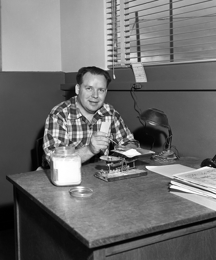
This insight into Ted Goodfellow comes to us from his daughter Robin.
My father, Ted Goodfellow, a silent key, started at Tektronix as a person to teach soldering. Being a ham gave him that skill. He also had had a pottery shop on the Oregon Coast, through which he had experimented with glazes and making his own electric kilns that would hold a certain temperature at a certain time for a certain length of time. This was an innovation not known in the industry at this time, around 1947 or so.
When he started working for Tektronix, he saw that there were problems soldering. He decided that there must be a better way to do things.
When he was developing the ceramic group at Tektronix, he spent a great deal of time at the main library in Portland, which used to be open until 10:00 most nights. He complained that he couldn't check the books out; the librarians insisted that he only use them there, which he thought was strange since he was sure nobody else had touched them for years!
He only had an 8th grade education, but he studied chemistry in the library and also with his experiments with glazes. He was very interested in all sorts of science. He was finally awarded an honorary degree from the University of Washington. After a few years of study and experimentation, he developed the ceramic strips.
A quonset hut on the Sunset campus was the location of the kiln and other process equipment for initial production of ceramic strips at Tektronix. Later, Building 13 (the current location of the vintageTek Museum) on the Beaverton campus was to be the much larger home for ceramic component manufacture.
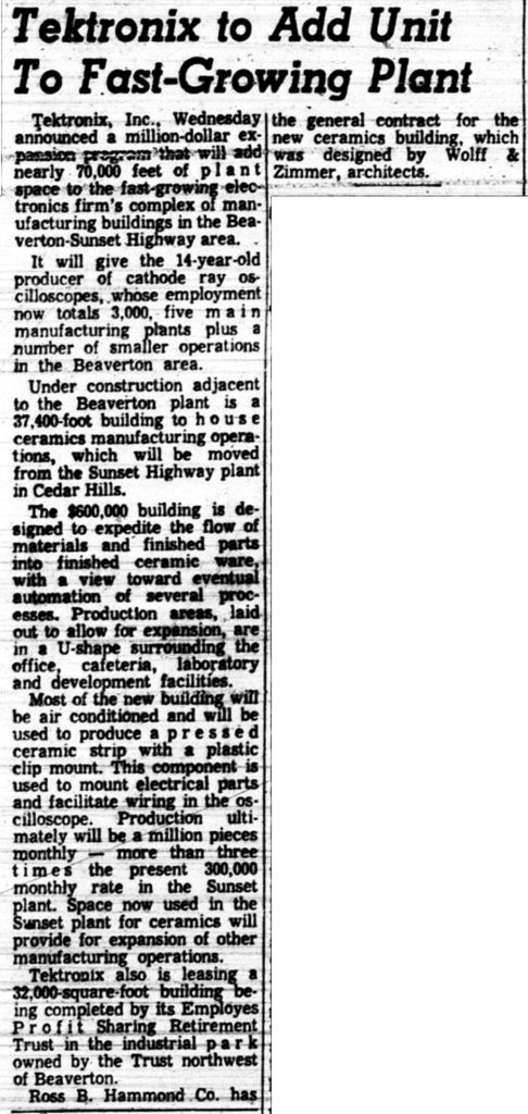
This August 20, 1959 Oregonian article describes the construction of Building 13.
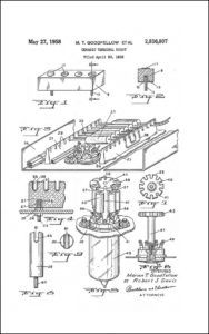
The first ceramic strips mounted using 2-56 threaded posts requiring a nut, a lock washer, and a jam nut to set the height above the chassis (two per strip). Later push-on plastic saddle posts with push-in collars replaced the cumbersome threaded posts. This later design also included the capability for a finer slot pitch to increase component density. U.S. Patent 2,836,807, issued on May 27, 1958, describes the ceramic strip and the mounting method. Click on the image below to view the PDF.
The first use of ceramic strips was in the Type 315 oscilloscope in 1952. During the
manufacturing process, silver in liquid form is painted in and on the notches of the strips prior to the application of the final glaze and final firing. The silver is then firmly bonded to the ceramic and wires can be soldered directly to the ceramic.
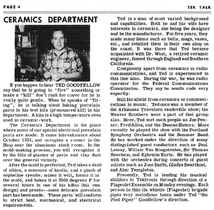
This February 1952 TekTalk features an article on the Ted Goodfellow and the Ceramics Department.
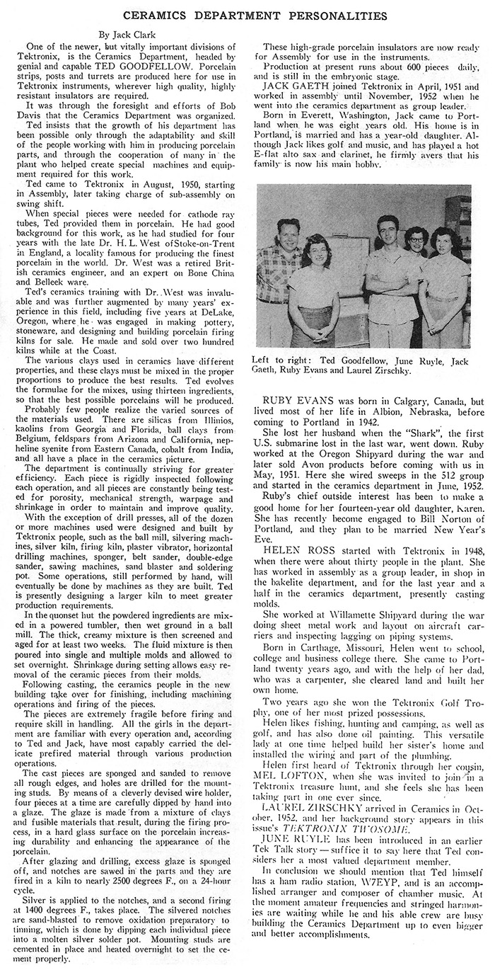
This November 1953 TekTalk features the Ceramics Department personnel.
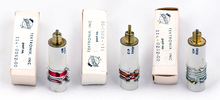
The 190 Constant Amplitude Signal Generator, introduced in 1954, used seven adjustable coils made with ceramic bodies. They are unique in that they used external snap rings as the solder points.
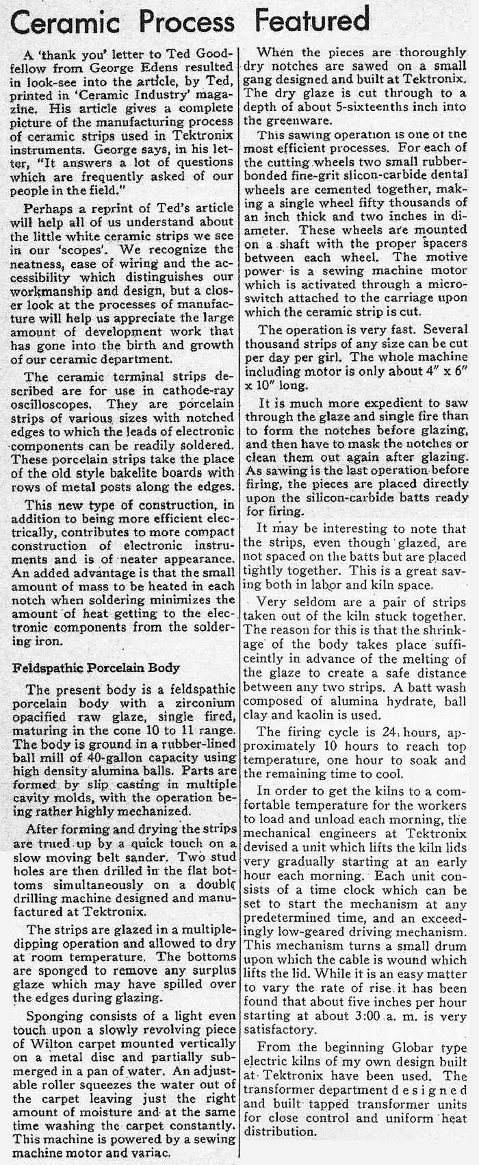
This October 14, 1956 TekTalk features a description of the ceramics process.
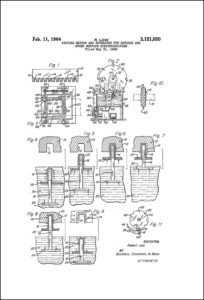
This later U.S. Patent 3,121,020 describes machine application of the silver paint to the strips. Click on the image to view the PDF.
Special silver-bearing solder is used to solder wires and components directly to the
notches in ceramic strips and has a composition of 60% tin, 37% lead, 3% silver. This silver-bearing solder should be used when soldering or repairing ceramic strips which prevents the silver bonded to the ceramic from dissolving in the molten solder. Failure to use the correct silver-bearing solder on Tektronix ceramic strips can result in failure of the silver to ceramic bond. Tektronix would include a small spool of silver-bearing solder for repair in some of its instruments. After assembly an air blast of ground walnut shells would clean ceramic strips of excess flux.
Ceramic strips proved to be quite reliable. However, under certain poor environmental conditions and with several hundred volts applied between adjacent notches, silver migration will occur leading to ceramic strip failure due to arcing between adjacent notches. The silver plating in the notches would migrate and form a bridge across the glazed ceramic between adjacent notches. Eventually, the bridge would break down and form a conducting path between the notches. The heat from the resulting arc would fire the silver into the ceramic causing a permanent short between notches. This short cannot be reliably cleared and the strip must be replaced. Migrating silver can be cleaned from a strip if it is done before it arcs.
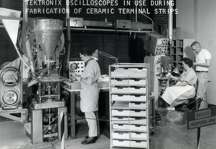
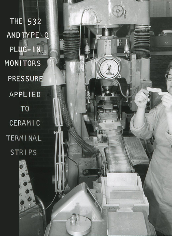
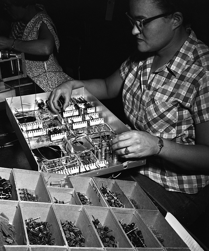
These two undated promotional photos show production of the ceramic strips.
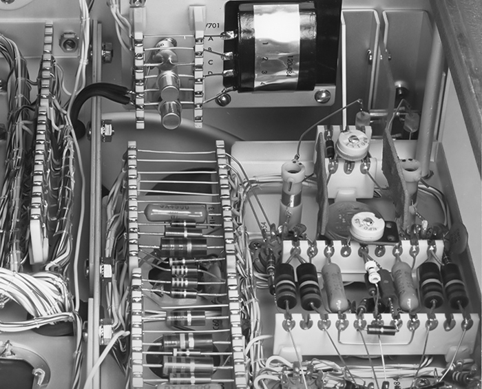
This photo shows assembly using ceramic strips. There is a 1964 film on Ceramic Strip Soldering Techniques on our Video Gallery.
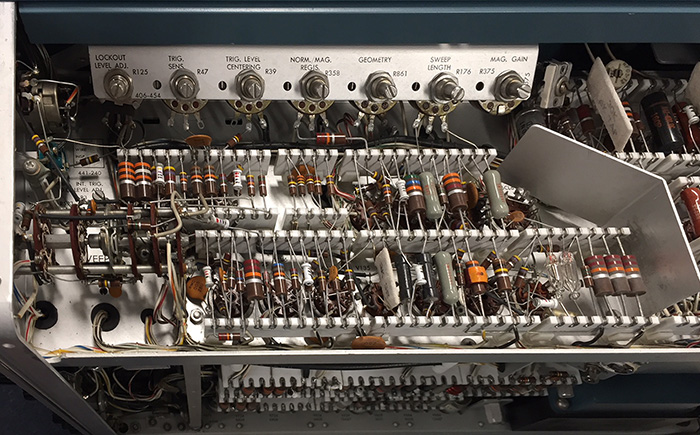
This image is the top view of the ceramic strips in the Type 545A oscilloscope on display at the museum.
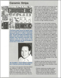
The Winning With People: The First 40 Years Of Tektronix has a nice summary of ceramic strips. Click on the image to view the PDF.
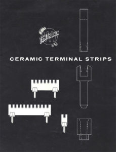
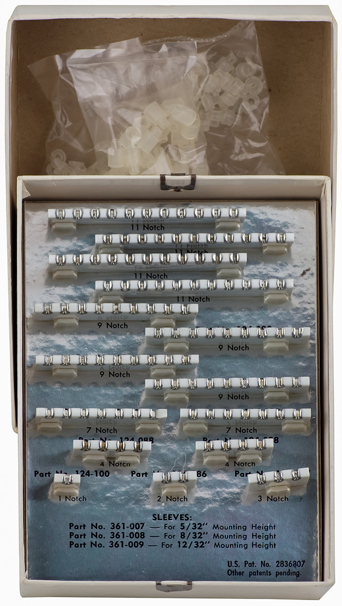
Ceramic strips continued to be used on some 7000-series instruments until the mid 1970s and plug-ins until the early 1990s. Ceramic Strips were also offered as components for sale. The museum has a ceramic strip demonstration kit and a 1959 brochure. Click on the image to view the PDF.
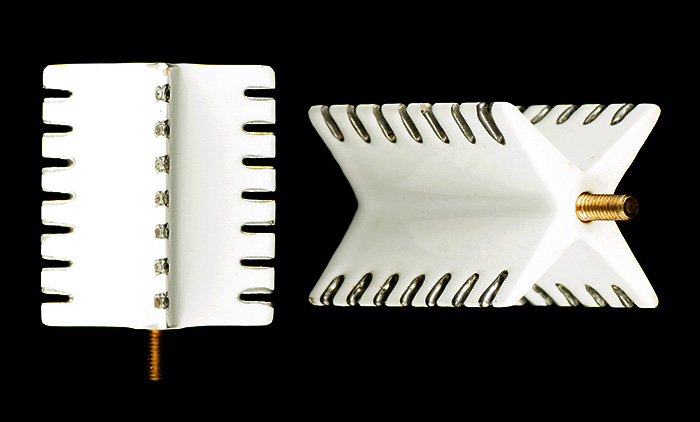
We have this mysterious X-shaped ceramic strip at the museum but we have no information of if or where it was used.
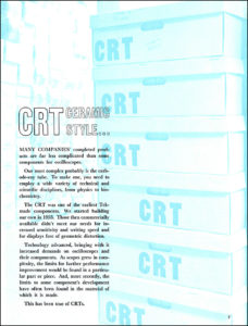
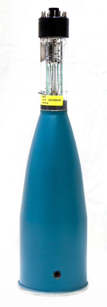
The in–house ceramic production expertise later presented Tektronix with another unique solution to a vexing problem. Glass funnels for scope CRTs were only available in a limited number of sizes and tooling for new glass funnel designs was very expensive – an expense that was difficult to justify for a low volume CRT. The ceramic operation would prove very valuable when ceramic funnels were developed in an effort lead by William Wilbanks in 1961. The first CRT with a ceramic funnel was the T5610 introduced in the 561A scope in 1962. This photo is of a round ceramic funnel CRT.
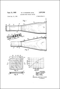
In less than a decade after production of the T5610 CRT, almost all of Tek’s CRTs employed ceramic funnels made internally. U.S. patent 3,207,936 was issued to Tektronix in 1965 for ceramic funnels. Click on the image to view the PDF.
This Winter 1970 TekTalk article describes the advantages of ceramic CRT funnels.
This July 9, 1982 TekWeek article features improvements to the material handling in ceramics operation. Click on the image to view the PDF.
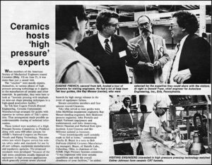
This July 29, 1983 TekWeek article describes a tour of the ceramics operation by members of the American Society of Mechanical Engineers. Click on the image to view the PDF.
Here is an inside view of the kiln room at the top of building 13. The kiln room has a very unique shape with large windows on the east and west sides.
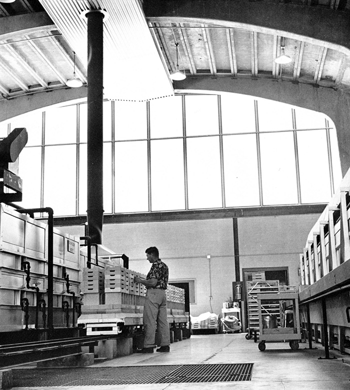
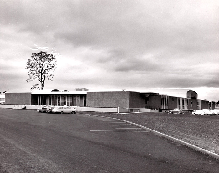
These three photos of Building 13 are from 1959. This photo is from the SE looking now a RAMS and vintageTEK.
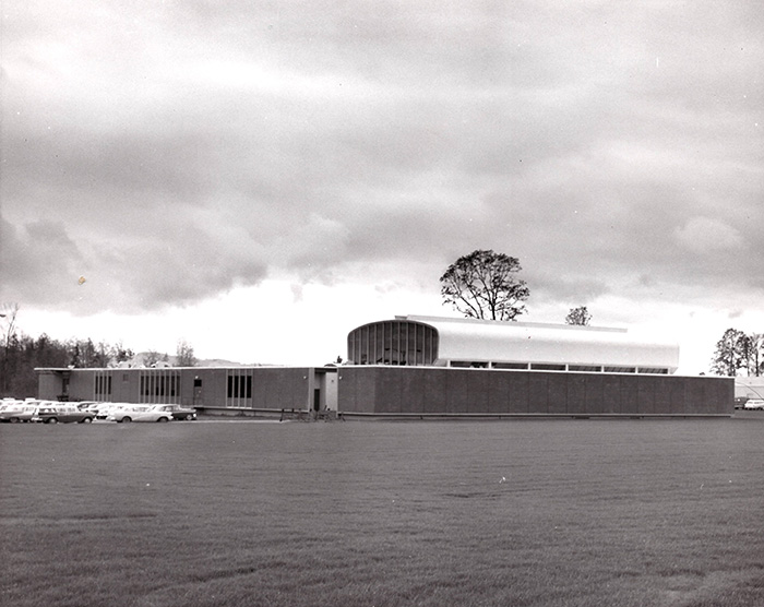
This photo is from the NW showing the kiln and the building before the addition.
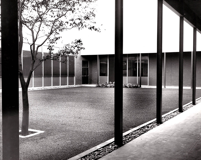
This is the only photo we have of the atrium which is now where the museum is located.
Starting in the 1980’s the ceramics operation sold ceramic components. This April 1983 brochure features some of the standard products and processes. Click on the image to view the PDF.
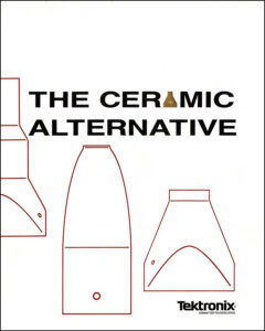
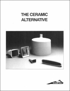
The ceramics operation was spun off in 1994 from Tektronix as Vispro Corporation, a supplier of LTCC multi-layer ceramic substrates and structural ceramic components. In January of 2000 Kyocera America, Inc. acquired VisPro Corporation. This VisPro Corporation ceramic CRT brochure is from 1994. Click on the image to view the PDF.

