The museum acquired a 100 year old General Electric Oscillograph, model PM-12-A6. The oscillograph is an optical-mechanical instrument for visualizing waveforms. It was originally used in AM radio stations for measuring percent modulation. It has about 10% accuracy and was expensive, costing over $1,000 in 2026 dollars. It has two channels for displaying both voltage and current.
Volunteer Matt Kamna restored the instrument which we now have on display. The oscillograph, along with our Early CRT Demonstration using a mid-1930s RCA CRT, shows the early history of viewing electric signals and the need for a better oscilloscope. This photo shows the top of the oscillograph as it is displayed on it's side and the cabinet is missing the lid. Click on the image to view a larger resolution PDF.
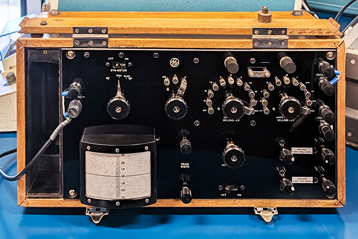
The instrument has an AC power switch and a 3-position rotary switch for lamp off, and two different lamp brightness settings. Another switch synchronizes the motor for a "triggered" sweep at 60 Hz line frequency. There are “vertical” and “horizontal” knobs that move the galvanometer’s physical position for positioning the image on the screen. Two additional ¼ turn knobs block the light of either light path, effectively turning that channel off, similar to the display MODE control on a modern oscilloscope.
The two large rotary switches set the current and volts per millimeter, equivalent to the VOLT/DIV on a modern oscilloscope. A shorting strap can be opened to measure the current with a meter. A 4-position switch allows for photography documentation when the viewing screen is replaced with a camera. On the upper left we've added an AC line cord with grounding and on the upper right we have picked off 60 Hz from the lamp transformer as the voltage input. The 3.5A lamp has been replaced with a high power LED. You need to view the screen in total darkness.
This photo shows the inside rear of the instrument. Click on the image to view a larger resolution PDF.
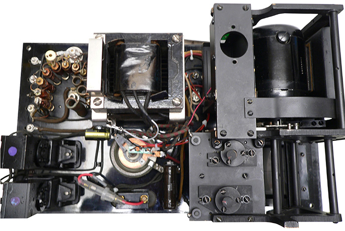
On the left are the two galvanometers, one for voltage, and one for current. These contain very tiny mirrors to reflect the light to another lens. One galvanometer mirror appears to be copper colored. We believe it either lost its silver mirroring or it makes for easier identification of the two channels similar to a modern color oscilloscope. You can see a new capacitor and fuse holder for the 120 V AC mains. The diodes and electrolytic capacitor were added for the LED voltage source.. This replaced the #1133 1926 Buick headlamp light source. At the #2 8V brightness setting the lamp was only rated for a 1 hour lifespan.
In the center is the rheostat for adjusting the motor speed up to 2200 RPM, equivalent to the horizontal TIME/DIV on a modern oscilloscope. It allowed viewing up to 4 kHz signals. On the right is the 1/200 Hp motor that drives a mirrored reflecting prism for scanning light to the screen. The motor also drives the 5” chopper wheel. The wheel lets light through 50% of the time and has six small steel disc’s spaced every 60 degrees. This aluminum chopper wheel passes through a ¼” opening in a big 60 Hz electromagnet for a clever way of obtaining a frozen/triggered display when synchronizing the motor.
This photo shows the inside top of the instrument. Click on the image to view a larger resolution PDF.
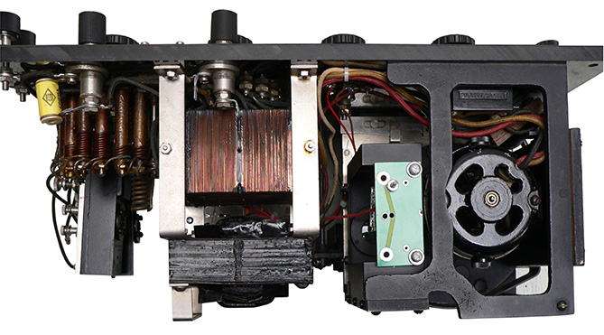
Above the power transformer you can see the precision wire wound resistors for the voltage divider string. Off to one side of these are the heavy gauge wire wound resistors for the current divider string. You can see a new adjustable position PCB with white LED mounted underneath. What you can’t see is the lens it shines through to adjustable mirrored prisms. The light then passes through two rectangular slots and out to the galvanometers. The galvanometer mirrors are suspended by two less than .001” silver wires. This tiny adjustable complex mechanical suspension is immersed in a dampening silicone oil and flanked between magnets. The screen light output is very dim due to inefficiency of the galvanometers.
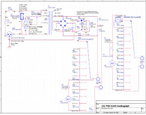
This is quite the instrument. Matt generated this schematic of the instrument along with our modifications. Click on the image to view the PDF.