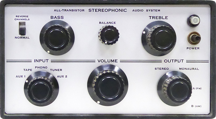
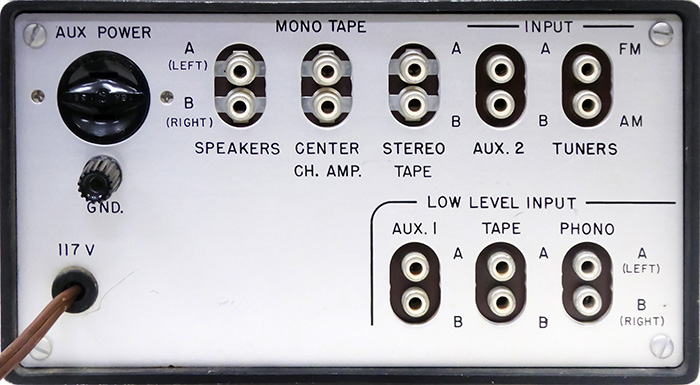
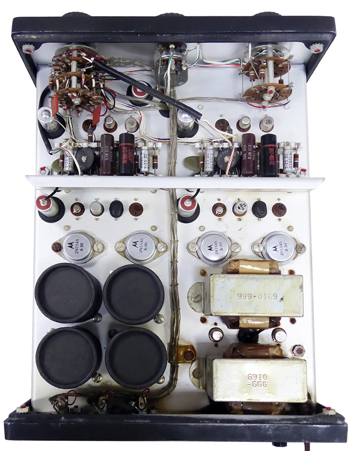
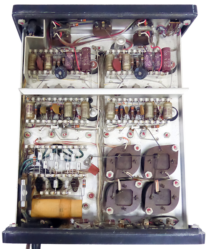
Tektronix was generous in the use of its facilities, model shop, stock room, etc. for personal projects, and with so many engineers, there were quite a number. In the late 1950s this Hi-Fi was designed as a personal project and a number of employees built their own.
It is a monolithic design consisting of a stereo preamplifier and power amp. The preamplifier features separate input selector and volume, base, and treble controls for each channel, and a stereo volume control in the center. These four photos are labeled Vylette Putman January 1959.
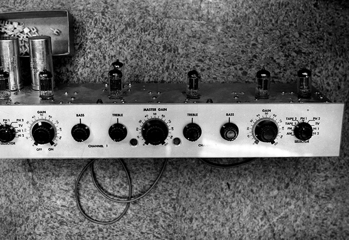
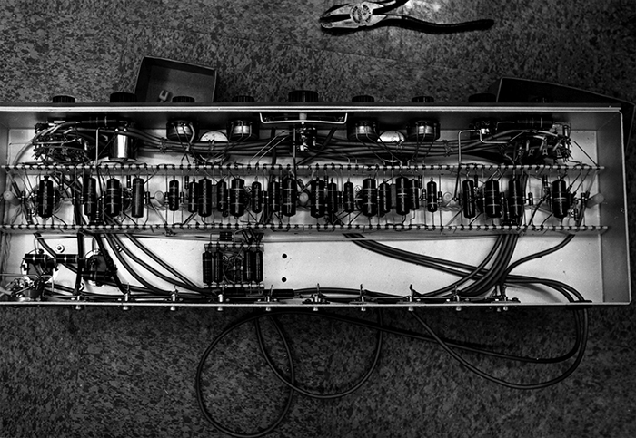
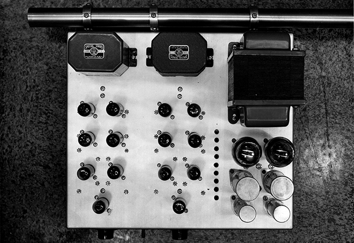
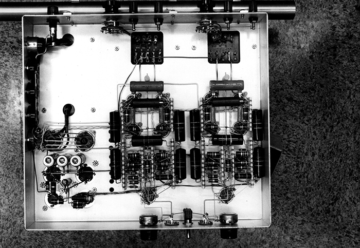
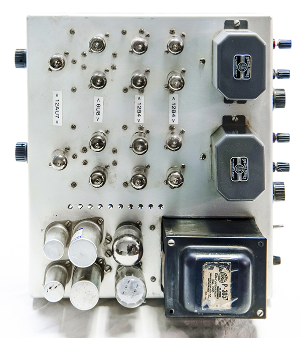
The power amp is a push-pull configuration using 12B4 triode tubes. These tubes were used as series pass regulators in Tektronix oscilloscope power supplies. The power amp has level controls for each input, although wired "backwards". The amplifier appears to be about 5 watts although the output transformers are rated for much higher. The power transformer delivers 425 volts which is then dropped to just 300V for the output circuitry.
These are various receipts for the parts personal purchase. Joe Varadi was an immigrant from Hungary who worked as a tool and die maker in the Plastics Department around this time frame.
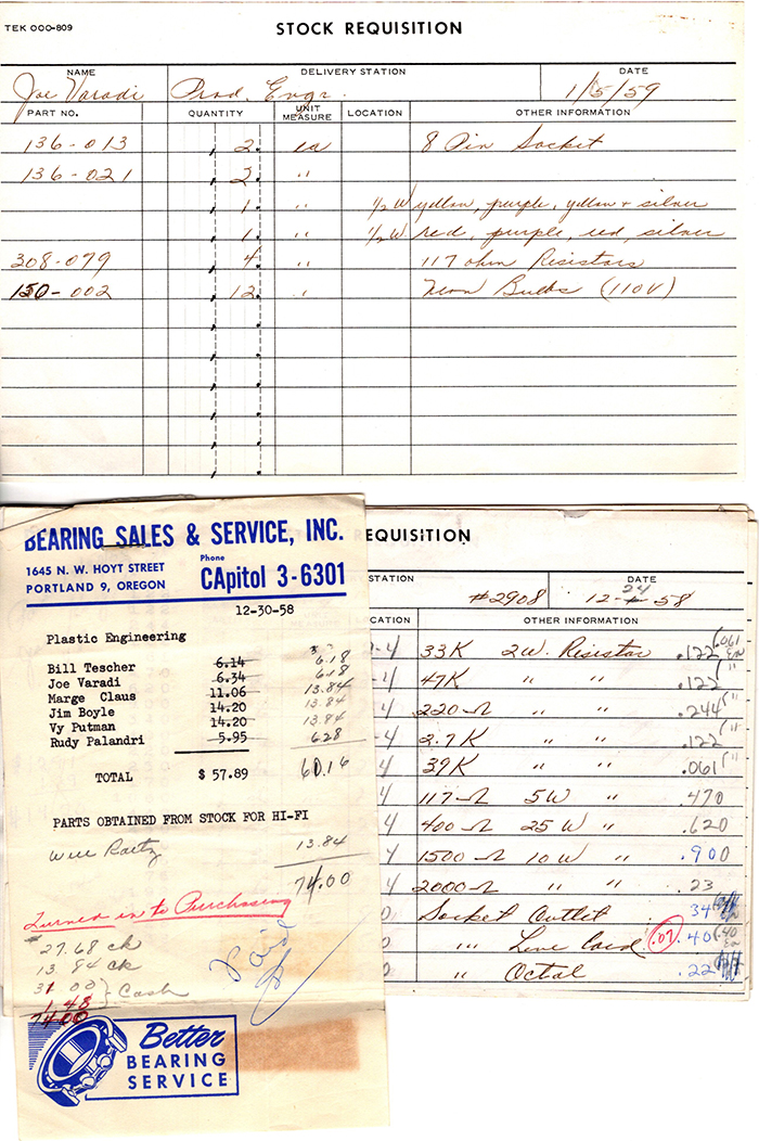
These documents provide the construction details. Click on the links to view the PDFs.
Preamplifier schematics February 20, 1960 and component placement March 31,1960
Power Amplifier schematics and component placement
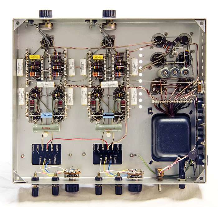
This set does not belong to the museum but came in for repair. The preamplifier has 5 inputs and no magnetic phono preamplifier. The gain with the tone controls centered was 4X. Treble increased the gain to 22X at 10 KHz and bass increased the gain to 34X at 100 Hz.
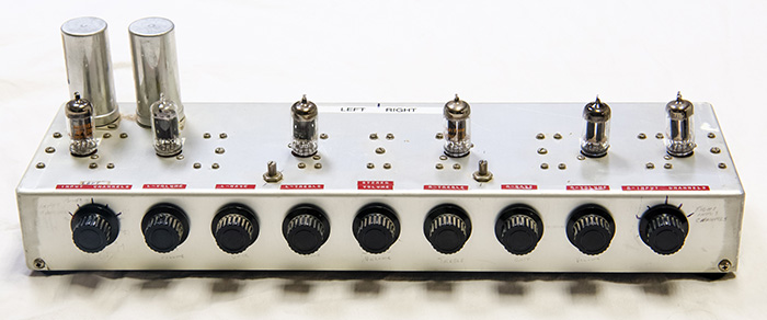
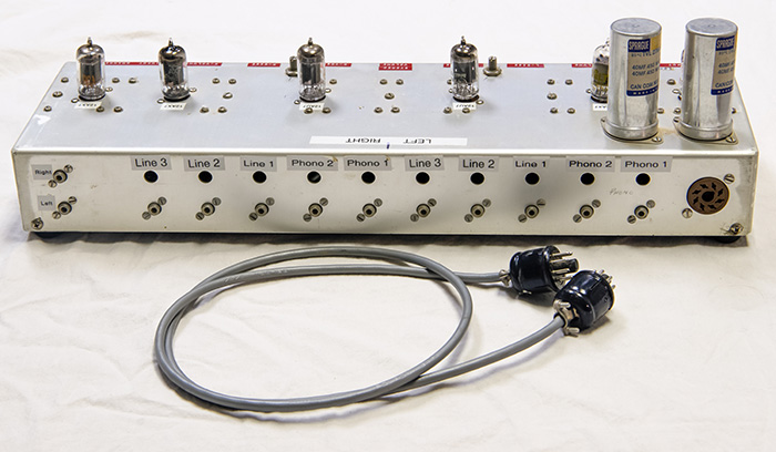
The original bumble bee capacitors have been replaced.
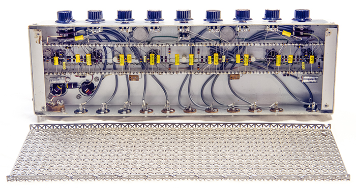
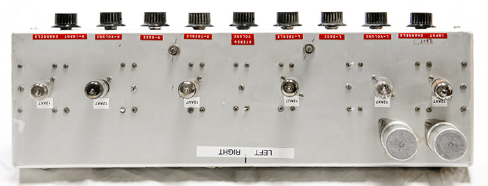
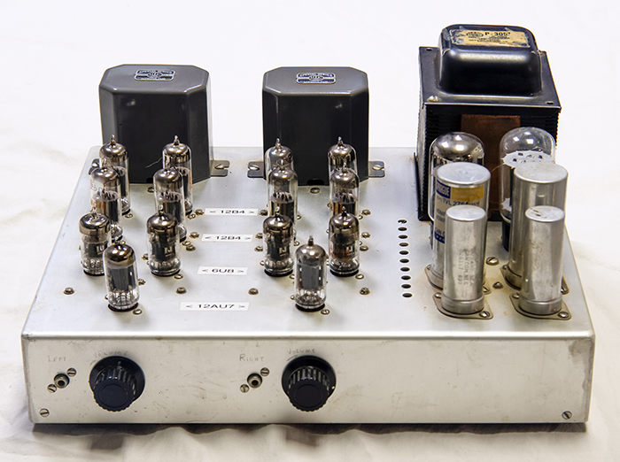
The power amplifier has speaker selectors for 4, 8, and 16 ohms as well as the AC switch and fuse. At 8 ohms, a 700 mV RMS signal produced 14.6 watts before clipping.
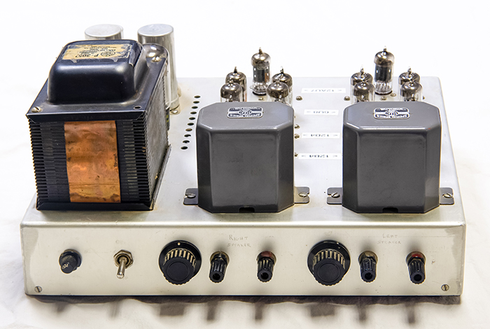
It also features several auxiliary AC outlets and the octal socket for power to the preamplifier. The AC connector has been changed to an IEC type.
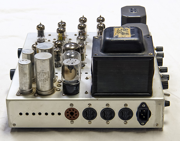
Like the preamplifier, the bumble bee capacitors have been replaced.
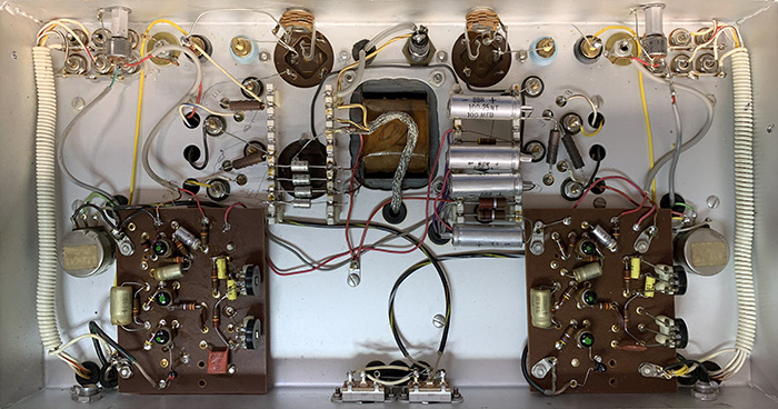
There are other examples of Hi-Fi amplifiers designed as personal projects. We do not know if this solid state version was a group build or just a single project. The front panel is similar to the tube version with separate input selector and volume, base, and treble controls for each channel, and a stereo volume control in the center.

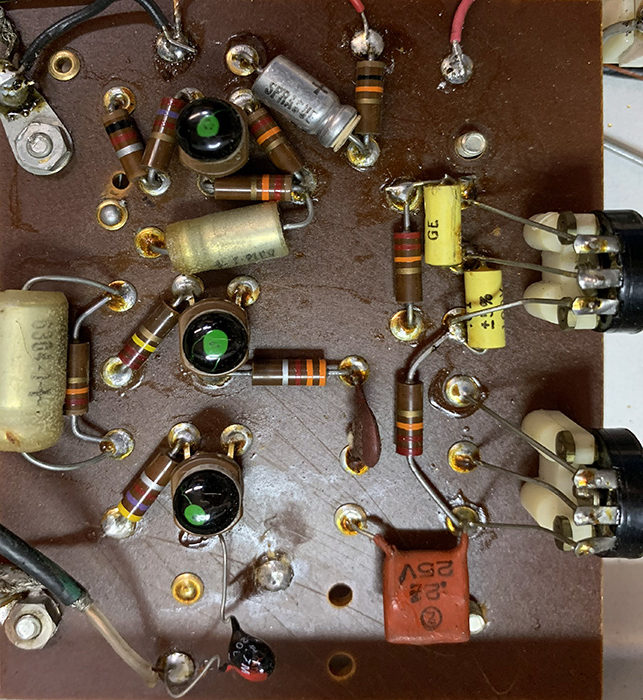
This version uses eyelet cards for point to point wiring.
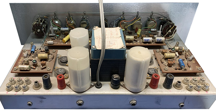
2N1529 output transistors are heat sunk to the chassis as is the 2N307 power supply regulator. These are both germanium transistors which dates this likely in the early 1960s. This amplifier uses an unipolar supply so the two rear capacitors are the DC blocking capacitors for the speakers.
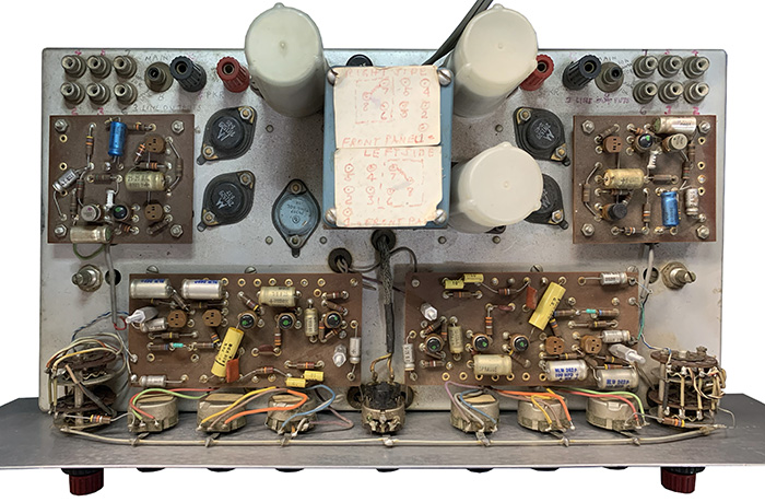
Ceramic strips are still used for the power supply. Note the fancy hand-wound shielded cables on each side.
Here's a view of one of the eyelet cards.
Here is another solid state example using ceramic strips.
