A detailed story of the development of the 200 series is on the Birth Of The Miniscope, by David Allen Employee's Stories page. Small portions of his story have been included below.
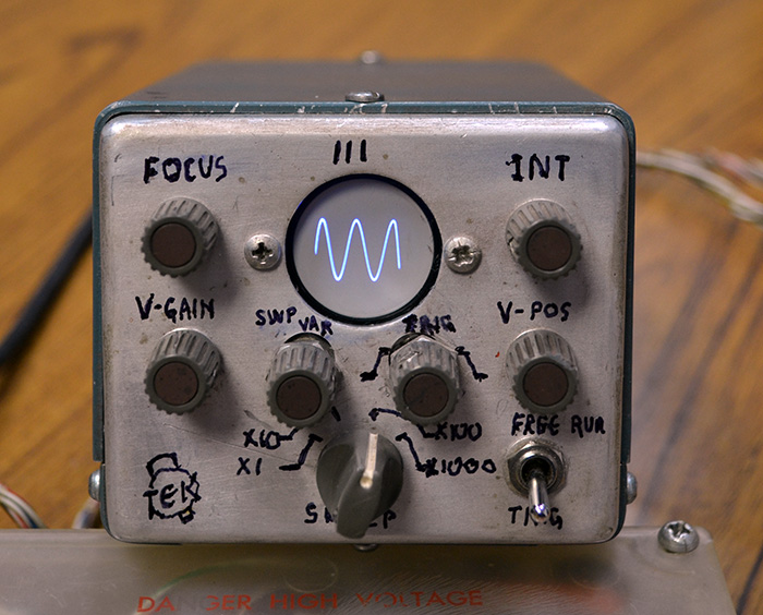
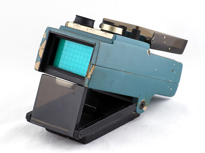
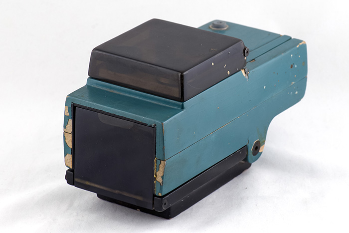
Howard Vollum thought small hand-held oscilloscopes could expand the market. The key challenges to such an instrument were a low power CRT, integrated circuits to minimize power and size, and a small package. This working handmade "miniscope" prototype was important in the 200 series initial development. Dave Allen restored it to working condition after almost 50 years of being ignored.
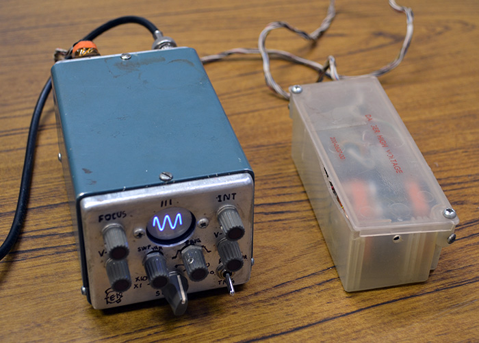
The power supply is in a small external box.
The first hand-held concept prototypes were simple cardboard models made by the Industrial Design group.
From Birth Of The Miniscope, by David Allen: All these conceptual prototypes were made by the Industrial Design group and each week we had another small model to look at. Some were made of cardboard and Styrofoam and others were shaped, painted, with see through tops and had actual turning knobs. I don’t recall exactly how the final format of the 200 series came about, but it had a good size control panel , a place to store the probe and a tilt stand for easy viewing - a more practical version of the futuristic previous models.
This concept prototype is more refined and very well constructed.
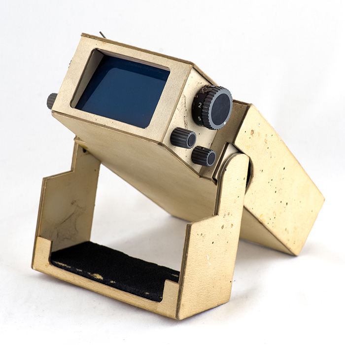
Note the detail of the cardboard probe inserted on the left side of the top.

This painted cardboard prototype shows another possible concept.
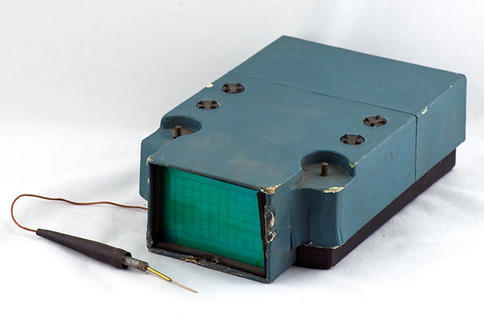
This concept prototype is an aluminum chassis machined in the model shop.
The package is a two piece clamshell design. Inside is another concept for an all-ceramic CRT. The concept for an all-ceramic CRT was never developed further.
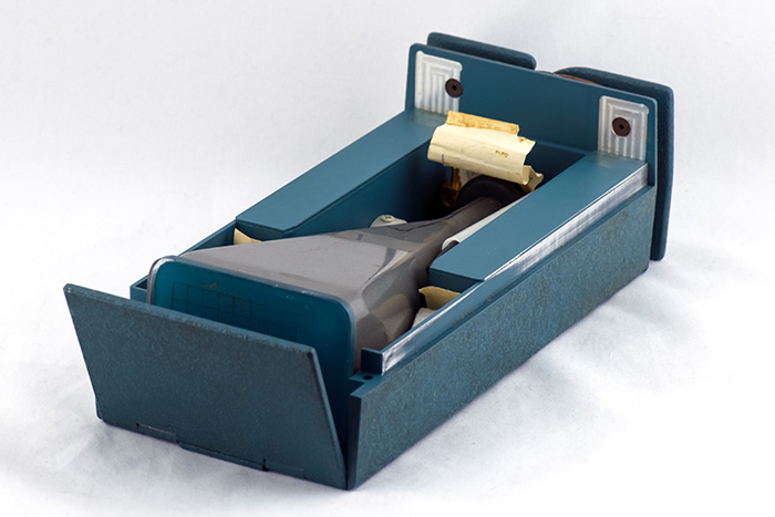
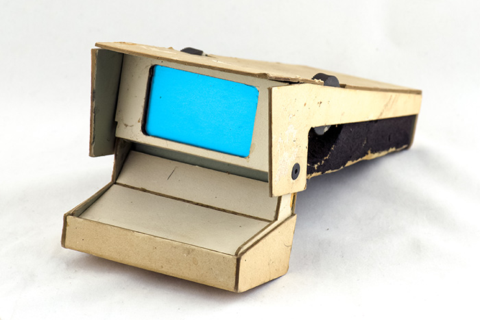
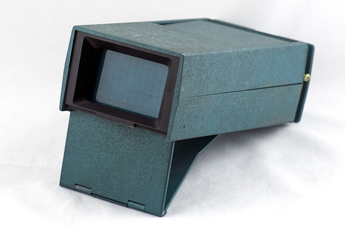
This more elaborate painted cardboard concept prototype has a hinged cover on top and a hinged bottom stand and folds up when not in use.
From Birth Of The Miniscope, by David Allen: One of the first design goals was to have the 200 series of oscilloscopes be double insulated - to be “floatable”. We advertised it as “floatable” and several “tongue in cheek” comments came back that someone threw it in water but “IT PROMPTLY SANK!”. The double insulated feature of the “miniscope” is why it has the plastic case. Every part of the electronics inside that connected to the AC power lines have at least two layers of insulation between the internal circuits and anything a user can contact. The charging circuit, the batteries and the primary of the internal power supply all float on the AC power line. Since the ground of the input probe could be attached to the AC power lines, all of the circuitry inside the unit had to have the same insulation to the outside of the unit where a user might touch. We had to have extra insulated slide switch covers, plastic knobs without set screws and any access hole had to be small enough. Product insulation was not that hard for the 211 as it only had one ground lead for the probe. But for a dual trace 212 and 214 we had to have a yellow ground leads for the two probes with special instructions that these two leads are internally connected together and should be used with caution when floating the instrument.
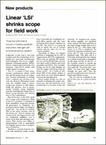
The 211 miniscope was introduced in the October 11, 1971 issue of Electronics as "a new low-in size, that is" oscilloscope. Click on the image to view the PDF.
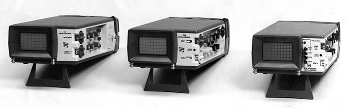
The 200 Series oscilloscopes did indeed open up a new market for Tektronix in hand-held applications. This promotional photo shows the initial 200 series family consisting of the 211, 212, and 214 500 KHz oscilloscopes. The 211 was a single channel, the 212 a dual channel, and the 214 a dual channel storage oscilloscope.
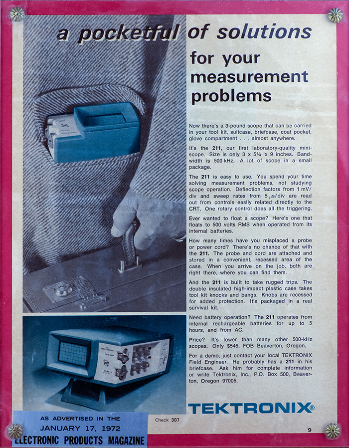
This framed copy is the original advertisement in Electronic Products magazine.
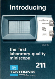
This 1971 brochure features the 211 miniscope. Click on the image to view the PDF.
From Birth Of The Miniscope, by David Allen: As production built these 200 series “miniscopes” I kept track of how many they had built. When the 1000th 211 was just about to be built, I asked if I could get the 1000th unit to give to Howard Vollum. As Electro-chem could do almost everything, I took several of the 211 enclosures over and asked them to gold plate them. Well, the process for applying gold on plastic required a little more heat than the plastic could endure. Several of the cases were badly warped so I picked the best ones, applied a little heat and pressure and made one set look just fine. The next hurdle loomed. As we all know, gold is NOT an insulator. The inside of the enclosure was now connected to the beautiful gold plating all over the outside. A gold 211 might be lethal if you plugged it in while holding it. With a standard Dremel tool, I removed a path of gold on the inside of the case about ¼ inch wide all around the edge so the outside was only cosmetic and not connected to the inner part. It looked wonderful!. I always wondered what Howard did with it.
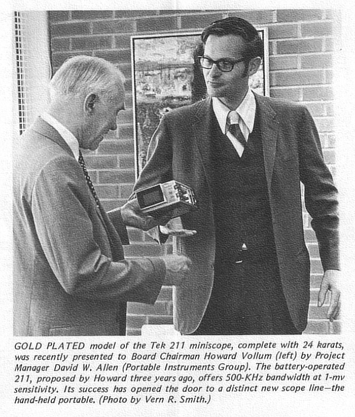
This July 21, 1972 TekWeek features a gold plated 211 oscilloscope presented to Howard Vollum by Project Manager David Allen.
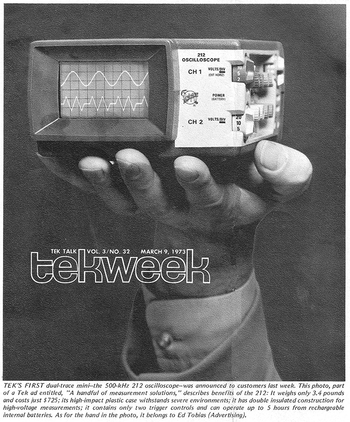
This March 9, 1973 TekTalk cover features the 212.
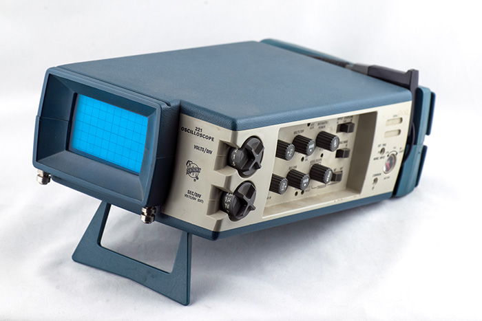
The 221, introduced in 1973, increased the bandwidth to 5 MHz. The museum has a 221 oscilloscope on display.
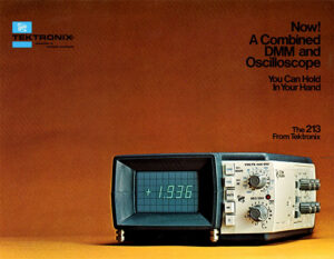
The 213 DMM oscilloscope was introduced in 1975. The museum also has a 213 DMM oscilloscope on display.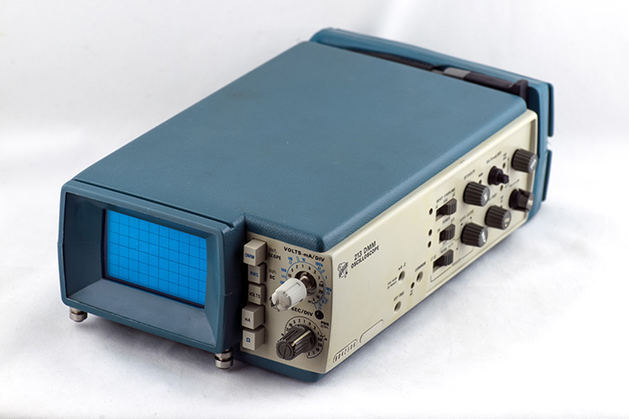
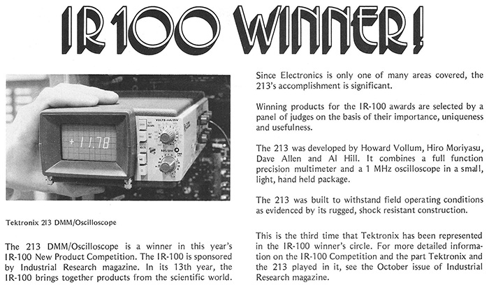
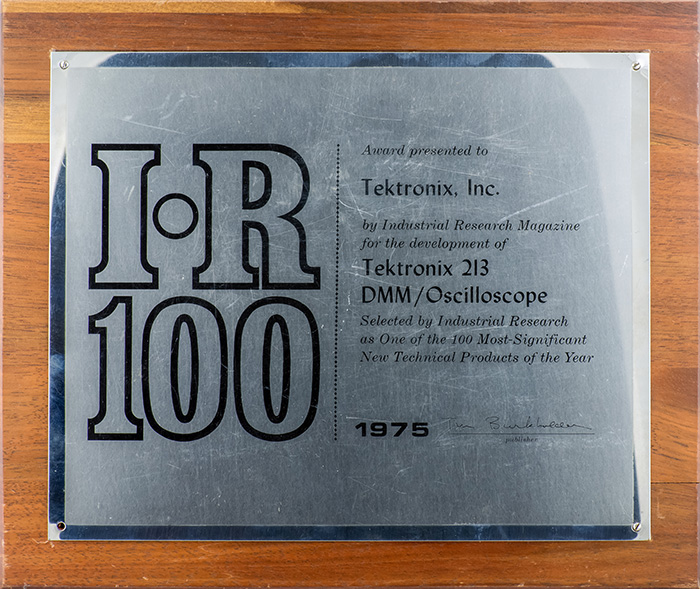
The 213 was selected by Industrial Research as one of the 100 most significant new technical products of 1975.
This 1975 brochure describes the features of the 213. Click on the image to view the PDF.
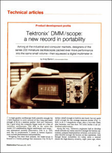
This February 20, 1975 Electronics article Tektronix' DMM/scope: a new record in portability describes the development effort. Click on the image to view the PDF.
There were a number of firsts that occurred on the 200 series development:
- Complete oscilloscope function integrated into a single IC (sweep circuit and output amplifiers)
- Double insulated scope specified to float up to 500V
- All plastic case held together with just 5 screws
- An attached probe and power cord with a convenient place to store them
- Two-gang rotary switches incorporated on the PCB
- Small sixteen pin IC package using all 4 sides (later used for high frequency designs)
- Simple vinyl carrying case for the oscilloscope, manual and viewing hood for easy handling
- Series of 5 different models: 211, 212, 214, 213 and 221
- Four function DMM (mA, DC V, RMS V, Ohms) integrated in a floatable oscilloscope
- DMM dynamic RMS conversion by Tektronix patented integrated circuit
- Fast turn on beam
- Low power consumption
- Use of Tektronix thin film ceramic resistors for 1% accuracy in the sweep and high voltage circuits
- Smallest storage oscilloscope
- First dual trace small oscilloscope
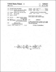
Two patents were issued pertaining to the 213 development. US patent 3,840,813 was issued to David Allen and Hideki IWata on October 8, 1974 for a Dynamic RMS Converter. Prior true RMS instruments were expensive and large. The dynamic true RMS measurement capability in the size and price of a 213 was a first .Click on the image to view the PDF.
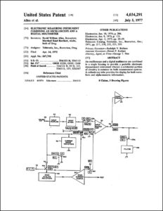
US patent 4,034,291 was issued to David Allen and Marshall Borchert on July 5, 1977 for an Electronic Measuring Instrument Combining An Oscilloscope and A Digital Multimeter. Click on the image to view the PDF.
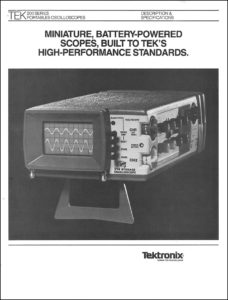
This May 1982 200 Series brochure covers the 211, 212, 213, 214, and 221. Click on the image to view the PDF.
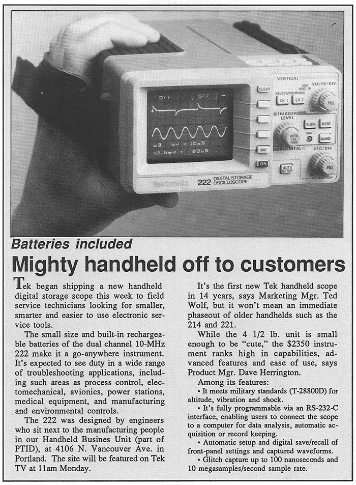
No new handheld scopes were introduced until the 222 in 1989. The 222 is a dual channel 10 MHz oscilloscope with isolated inputs and advanced features. This January 13, 1989 TekWeek describes the 222 oscilloscope.
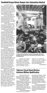
This January 8, 1993 TekWeek features an article on the 222 used in an automotive application. Click on the image to view the PDF.
The 208, 211, 212, 213, 214 and 221 CRTs incorporated the directly heated cathode introduced in the Sony/Tek 323 oscilloscope to minimize power consumption in these battery-operated instruments. The directly heated cathode was originally developed at Sony and introduced to Tektronix by the Sony engineer who designed the 323 CRT in Beaverton.
The electron guns in the 211, 212, 213, and 214 CRTs were the same; the 208 and 214 bistable storage CRTs were identical except for the graticule, and also used a directly heated cathode for the flood gun.
The CRT in the 208 and 214 was the first DVST to use a rare earth phosphor (P44) with excellent life and efficiency and needed a “Raised Web” structure because the phosphor was too conductive to be in contact with the collector electrode.
The 213 had a rare earth phosphor (P43) because it was expected to have continuous use with digits in the same area of the screen (“burn-in”); this phosphor was very stable and could tolerate the DMM plus oscilloscope application.
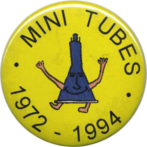
This 1994 pin marks the end of the miniscope CRT production.
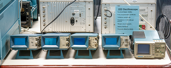
We have a display of five 200 series oscilloscopes at the museum. Left to right: 221, 211, 214, 213, 222.
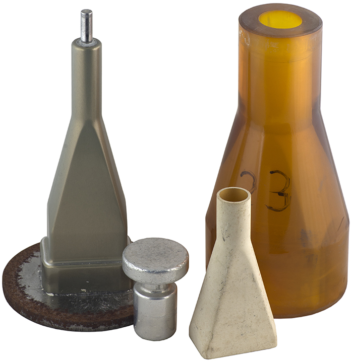
We also have on display the mold for the 200 series CRT ceramic funnel.