
by Phil Crosby
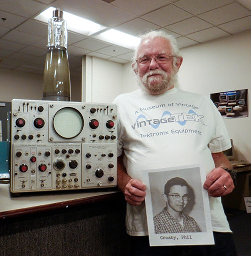
Phil Crosby then and now, with a Tektronix Type 556 and spare
CRT at the vintageTEK Museum in Beaverton, Oregon.
I was sort of the "loose ends" guy, so I was involved with most aspects of the instrument. I had finished the RM529 TV waveform monitor, a project for which I was fully responsible. I was going to do the cabinet version as well, but when it became apparent that the 556 was more difficult than expected, I was asked to join in.
Oliver Dalton, Bob Rullman, Gene Kauffman, and George Smith had done the 544, 546, and 547 mainframes and they felt that the 556 would be a walk in the park. Oliver had dreamed up the sweep switching trick1 for the 547 and felt that a dual beam oscilloscope should be able to present the same sort of display, but these people had more important things to do, so the 556 project got handed to the TV group under Charlie Rhodes in the belief that, except for the power supply, which would be a difficult packaging job requiring efficient heat removal, it should be a trivial exercise. The power supply was indeed challenging, but it was not the only challenge. The vertical amplifiers, sweep switching, and horizontal amplifiers all required significant
attention.
Challenges in the Power Supply
One clever aspect was the heat sink for the series pass transistors. Since they were originally germanium devices (DTG2400), it was imperative that they be kept as cool as possible. Their heat sink was a thick piece of aluminum, bent into a right angle (I never saw the bending brake) and mounted transversely to the air stream, very close to the fan. Slots sawn into the part bent away from the power transistors efficiently coupled heat into the air stream. The power transformer had a thick aluminum plate amidst its steel laminations used as a flange to tie to the sides of the two plug-in compartments.
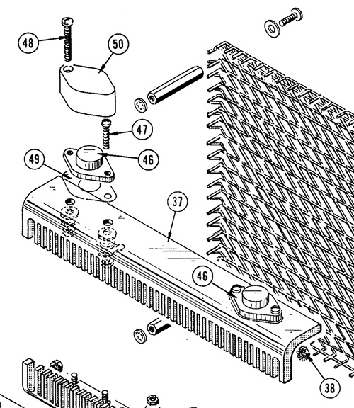
Power transistors (46) mounted on bent aluminum (37) with slots sawn
into it. Air flow from the air filter passes through the slots.
Challenges in the Vertical Signal Path
Relative to the 547, the CRT required extensive electrostatic shielding to prevent crosstalk between the two beams. The increased inter-electrode capacitances meant that the existing 547 solid-state vertical amplifier just couldn't deliver the required bandwidth and voltage swing. At that time, we had a requirement that full-screen step response should display minimal changes as it is positioned vertically over the screen area. We needed a hybrid transistor-tube cascode configuration. The Amperex 8233 power pentode had the requisite gm, but the output C was too high and it would be a lot better if some of the anode metal was trimmed away and the anode lead came out the top of the envelope, allowing a more direct path to the deflection plates and allowing more cooling for the 1k load resistors. We talked with Amperex and they agreed to do the mod calling it the 8608, which also found a home in two other Tektronix products: the 3A7 plug-in and the 549 storage scope.
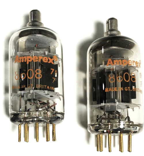 A pair of 8608 tubes.
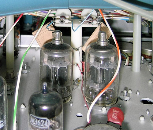 The vertical output tubes. The beige rectangular components are 1kΩ
plate resistors. In addition to reducing parasitics, moving the anode
connection to the top on the 8608 tube allows the plate resistors,
which dissipate a few watts, to be in the air stream from the fan.
Oliver’s requirement to emulate the 547 sweep switching feature in the dualbeam 556 meant that BOTH sets of vertical plates would have to optionally be driven from the same (right) plug-in. Low-capacitance diodes would optionally switch in a crossover amplifier driving the lower beam vertical amplifier as well. The increased number of amplifier stages meant that PNP stages were needed to keep the common-mode DC level, already elevated due to the vacuum tube output stage, from increasing further. At that time, no silicon transistors were available that could meet the speed and voltage requirements, so we were constrained to use the 2N2929, a PNP germanium transistor that could barely meet the voltage and power dissipation requirements2. The seven or eight inches of 93 ohm coaxial cable required a couple of additional time constants to compensate for skin-effect loss.
Another germanium limitation was in the power supply's series pass transistors, where the Delco DTG2400 PNP transistor was the only suitable part available. After a break at serial number 2000, a major mod replaced the germanium parts with a design incorporating newly available silicon devices.
An aside – in the design of bleeding-edge electronic equipment, there can be a few bright ideas, followed by “yeahbuts”, as in, “yeah, but you’re gonna have to … “. Some projects end up staggering under the sheer load of the “yeahbuts”. The recent Boeing 737Max debacle comes to mind with its problems associated with engine placement, ground clearance, and thrust centroids, oh, and various kinds of cost issues. It’s one of those things that cause most designers to revere the Dilbert comic strip.
Challenges in the Horizontal Signal Path
Many vertical plug-ins employed an “ALT” mode, where the input channels are switched (A to B, Ch1 to Ch2) after the end of a sweep at a time when the beam is turned off hiding the visibility of the transition. However, if a single plug-in drives both beams, and the two sweeps run independently and asynchronously, there may be no time when neither sweep is running. In our function truth table, this became “note 5”, demanding the least worst solution. Accordingly, I designed logic ensuring that the A (delaying) sweep could not run until the B sweep had entered the holdoff state or was waiting.
Since the 500-series plug-in oscilloscopes had a 67.5 V plug-in/mainframe common-mode DC level, the possibilities of destruction of expensive solid-state devices due to a misplaced probe were rampant, often resulting in a string of expletives. Attempting to moderate the situation, we instituted a “cuss box” requiring a five-cent donation per cussword. The proceeds were intended to buy gifts for the prototype support people who had to wrestle with an 80 pound prototype. One member of the design team, renowned for his taciturn nature had contributed nothing to the cuss box until the evening when I heard a sound across the way similar to the sound that had resulted in my feeding about a dollar to the cuss box. I went over to see what had happened, and I saw the fellow shaking his finger at the part of the circuit where my errant short had occurred. He was getting redder by the second, prompting me to say, “you gotta let it out!”. He walked over to the cuss box and loudly said. “Damn!”, put a nickel in. Then he thought about it and said “Damn!” again, dropping another one in. He looked at me and said, “I feel much better now”.
Nearing Christmas of 1965, our operating rule was 12 hours a day, except for Thursday when “Batman” and “Lost in Space” were on the TV. One of us would stay home to watch and report to the others what had happened. Nobody (almost) should work on the weekend.
Another piece of “black magic” concerned the horizontal output amplifiers, similarly burdened with excessive CRT capacitance. Although we were squeaking by at the highest sweep and mag settings, I noticed that the apparent p-p amplitude of a sine wave decreased by a few percent as the envelope swept across the screen. The Horizontal output devices were cathode followers. I found that the negative-going output cathode follower was late in following the ramp, causing the electron beam’s axial velocity to increase due to the increased common-mode voltage, reducing the deflection sensitivity. The design, first appearing in the Tektronix 531, employs a pentode whose grid, driven by the differentiated positive-going ramp, boosts the pull-down current, keeping the cathode follower in conduction. Our circuit had been inherited from the 544-546-547 ‘scopes, and when I questioned the designer about the effect, he said, “I always wondered … “. Some fiddling with currents and time constants diminished the effect.
Brought to Market
In the initial release of the 556, We managed to meet the design specifications and then some, but we knew that the germanium transistors were a compromise. Two years later we replaced the germanium PNPs with silicon, producing a product that we felt a lot better about. Serial number above 2529 indicated the change.
The 556 was used extensively by the folks that were doing nuclear effects testing and they had stringent requirements for small spot size and high photographic writing speed, a combination that its replacement, the 7844, was unable to meet until its CRT was modified a few years after its introduction, so the 556 was the last of the 500-series mainframes to end production.
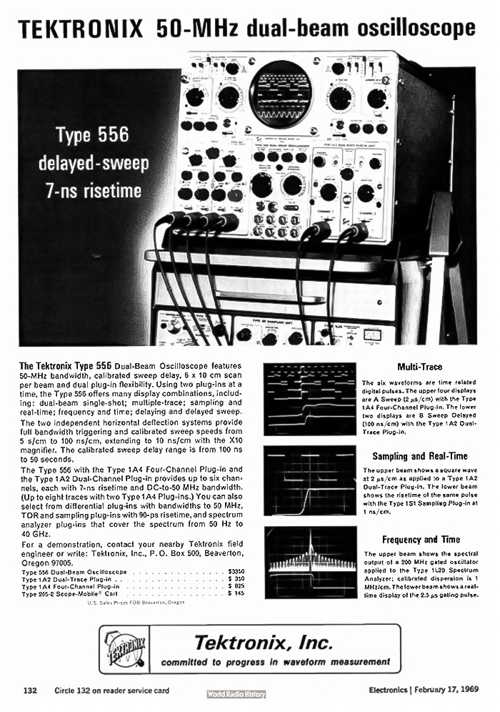
This ad for the 556 is from the February 17, 1969 issue of Electronics magazine.
1In "ALT" sweep mode on a 547, with a compatible plug-in such as a 1A1, input channel A is displayed using the A sweep and input channel B is displayed using the B sweep. This has value when probing two signals that fundamentally operate at different timescales, for example the IF and AF (or video) of a superhet receiver. However, since there is only one beam it is easy to determine when to switch channels in “ALT” mode.
2In the mid-60s, Tektronix had no resident IC design or fabrication facility, leaving us constrained by the availability of discrete transistors. The speed, voltage, and power dissipation requirements of the output devices, together with the need for high writing speed and small spot size always limited the performance of vertical amplifiers.